
Dold 0063630 MK9300N.11/022 time relay 3AC20-440V
Industrial Material > Industrial relays and contactors > Industrial Timers
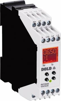
Dold 0063630 MK9300N.11/022 time relay 3AC20-440V
| Lieske Part No. | 1329145 |
|---|---|
| Mfg Part No | 0063630 |
| EAN-Code | 4030641636302 |
| Manufacturer | Dold |
| Here only | 313,93 EUR
373,58 EUR incl. VAT
|
Further information for Dold 0063630 MK9300N.11/022 time relay 3AC20-440V
| Technical data | |
| 1- / 3-phase | 1, 3 |
| Enclosure design | Switch cabinet |
| Measuring range max. | 400 V |
| Output contacts | 1 C/O contact |
| Standard measuring range | 3 AC 24 - 400 V |
| Width | 22,5 mm |
| Type | MK 9300N |
| Operate delay | |
| Variant | |
| Auxiliary voltage | DC 24 V |
| Contact equipping | 1 changeover contact |
| Measuring current | AC 12 A |
| Measuring voltage | 3AC 24 - 400 V |
| Terminal type | screw terminal fixed |
| Approvals and Markings | DNV |
Applications
This measuring relay is suitable for monitoring single- and three-phase electrical consumers, particularly in installations with motor loads, where symmetrical phase loading is common. It is frequently used in emergency power supplies, voltage-dependent switching operations, and for motor protection in case of phase faults. Monitoring of mobile consumers and transformer protection under unbalanced loading are also typical applications. The devices are designed for use in industrial environments where high operational reliability and availability are required.
Functions and Equipment in Detail
The device offers minimum, maximum, or window monitoring for voltage and current, with integrated response delay and an adjustable hysteresis of 0.2 to 50 % of the response value. The start-up bypass time prevents unwanted tripping during commissioning. Fault diagnosis is performed via an LCD display showing current measurement values, and an LED display indicating operating status: green LED for present auxiliary voltage, red LED (flashing) for overload in the current path, and orange LED in input mode. A fault memory enables tracking of tripping events. The relay function can be switched between operating and resting current, allowing the output logic to be adapted to the requirements of the installation.
Technology Explained Simply
Measurement is performed via fixed screw terminals, ensuring a secure and durable connection. The measuring voltage is connected to terminals L1/L2, with a minimum voltage of 20 V required to ensure proper function. For single-phase operation, terminals L2 and L3 must be bridged. The output relays are designed as changeover contacts, enabling flexible wiring. The monitoring functions are independently adjustable, allowing, for example, overvoltage monitoring with resting current principle or undervoltage monitoring with operating current principle to be configured. The devices comply with the standard EN 60255-1 and are certified with DNV approval.
Compatibility and Accessories
The MK9300N is part of the VARIMETER PRO series and can be combined with other devices in this series, particularly with the MH 9300, which offers two relay outputs. Optional plug-in terminal blocks are available, enabling easy replacement of the devices. The terminal type is fixed screw terminals, ensuring a robust connection. The devices are designed for use in enclosures and can be mounted in standard enclosures with a width of 22.5 mm.
Mounting and Installation
Mounting is performed in enclosures using the designated mounting elements. The connection terminals are designed for secure connections, with fixed screw terminals ensuring a durable connection. The terminal assignment is clearly defined: auxiliary voltage is connected to A1/A2, measuring voltage to L1/L2 (for three-phase operation) or L1 (for single-phase operation, with L2/L3 to be bridged). The output relays are connected to terminals 11, 12, and 14. Parameterization is performed via the device's menu structure, ensuring intuitive operation.
Operational Advantages
Simultaneous monitoring of multiple parameters increases operational safety. Early detection of irregularities enables preventive maintenance and prevents costly damage. Reduced wiring and compact design lower installation costs. Integrated fault diagnosis and fault memory simplify troubleshooting and maintenance. The devices are designed for industrial environments and offer high reliability during continuous operation.

This is an offer of:
79279 Vörstetten
https://industry-electronics.com
Tel. 07666/88499-0
Fax. 07666/88499-111
Diesen Artikel finden Sie unter:
industry-electronics.com/artikel/1329145

Lieske Elektronik e.K.
Reutener Str. 1079279 Vörstetten
https://industry-electronics.com
Tel. 07666/88499-0
Fax. 07666/88499-111
Diesen Artikel finden Sie unter:
industry-electronics.com/artikel/1329145