
Dold 0059710 GF9016 3AC50/60Hz 400V 15kW soft starter
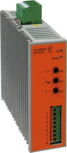
Dold 0059710 GF9016 3AC50/60Hz 400V 15kW soft starter
| Lieske Part No. | 1002146 |
|---|---|
| Mfg Part No | 0059710 |
| EAN-Code | 4030641597108 |
| Manufacturer | Dold |
| Here only | 614,63 EUR
731,41 EUR incl. VAT
|
Further information for Dold 0059710 GF9016 3AC50/60Hz 400V 15kW soft starter
| Technical data | |
| Extra functions | Mains monitoring, Temperature monitoring |
| For three-phase motors, 400 V up to | 22 kW |
| Load voltage up to | 3AC 400 V |
| Width | 45 mm, 52,5 mm |
| Type | GF 9016 |
| Signalling output | |
| Variant | |
| Auxiliary voltage | Without |
| Mains / motor voltage | 3AC 400 V |
| Nominal motor power | 15 kW |
| Approvals and Markings | UKCA |
Soft start and soft stop function
The device achieves a smooth start-up through phase-cut control using power semiconductors (thyristors). Two motor phases are controlled, causing the currents and motor torque to increase gradually. This prevents jerky acceleration and protects drive components such as gearboxes, belts or chains from mechanical wear. After start-up, the circuit is bridged via internal relay contacts to minimize power losses in the device. The soft stop function extends the natural coast-down time of the motor to avoid abrupt stopping and associated counter-torques.
Functions and equipment in detail
The device offers separate adjustment options for start-up and stop time as well as for start-up voltage. Optionally, a kick-start function can be activated to support the start-up process. Control is performed without auxiliary voltage, simplifying installation. The W3 circuit is possible, enabling flexible integration into existing systems. An alarm output is integrated to relay operating states and faults to external systems.
Technology explained clearly
The control is based on phase-cut control, where the voltage to two motor phases is controlled while the third phase remains directly connected. This leads to controlled current increase and uniform torque build-up. The integrated network monitoring and temperature monitoring ensure safe operation. In case of faults, a yellow LED blinks at a specific frequency indicating the fault code – for example, supply voltage fault, overload or defects in the power semiconductors. A green LED indicates the ready-to-operate state.
Compatibility and accessories
The device is designed for three-phase asynchronous motors with a rated voltage of 400 V and can be used in systems with gearbox, belt or chain drives. Typical applications include conveyor belts, fans, pumps, compressors, woodworking machines, centrifuges, packaging machines and door drives. Conformity with the standard IEC/EN 60947-4-2 ensures compliance with relevant safety and functional requirements.
Mounting and installation
Mounting is done in standard enclosures. The width of 45 mm allows for compact placement. The connection terminals are clearly labeled: L1, L2, L3 for supply voltage, T1, T2, T3 for motor voltage. Signal inputs and outputs (X1 to X8) serve for control and status indication. Terminal designations are detailed in the datasheet.
Advantages in operation
Through smooth start-up and shut-down, mechanical wear on motors and drive components is reduced, increasing service life. The relief of the network through reduced inrush currents reduces the load on the supply infrastructure. Simple installation without auxiliary voltage and compact design facilitate installation in existing systems. Integrated fault diagnosis via LED indicators enables quick fault resolution.
Approvals and markings
The device carries the UKCA mark, confirming conformity with applicable European safety and environmental requirements. Compliance with the standard IEC/EN 60947-4-2 ensures reliability and functionality in industrial use.
Application areas
The device is designed for industrial applications, particularly in machines with mechanical drives, such as conveyor belts, pumps, fans, compressors, packaging machines and door drives. It is suitable for systems where smooth start-up and shut-down are required to avoid damage to mechanical components.
Additional functions
The integrated network monitoring and temperature monitoring ensure safe operation. The alarm outputs enable integration into higher-level control systems. The W3 circuit expands application possibilities in complex system structures.
Device type and identification
The device type GF 9016 is specifically designed for use in three-phase networks with 400 V and motor powers up to 22 kW. The variant described here is designed for 15 kW and meets the manufacturer's technical specifications. The width of 45 mm is standardized for this power class.
Connection and control
Control is performed via signal inputs X2 (Start/Stop) and X3 (Kickstart). Outputs X5/X6 and X7/X8 serve for fault and status indication. Supply voltage is connected via L1, L2, L3, motor voltage via T1, T2, T3. Terminal designations are detailed in the datasheet.
Fault diagnosis
The yellow LED blinks in a specific pattern to indicate faults. A blink frequency of 1x per second indicates a supply voltage fault or insufficient load. 2x blinking indicates overload or excessive heatsink temperature. 3x blinking indicates an electronic fault. 4x and 5x blinking indicate ignition faults in phases 1 and 3 respectively. 6x and 7x blinking indicate faults in motor phases or defective power semiconductors. 8x blinking indicates a general synchronization fault.
Operational safety
The integrated network and temperature monitoring ensure safe operation. The alarm outputs enable connection to external monitoring systems. Conformity with IEC/EN 60947-4-2 ensures reliability in industrial use.
Approvals
The device carries the UKCA mark, confirming conformity with applicable European safety and environmental requirements. Compliance with the standard IEC/EN 60947-4-2 ensures reliability and functionality in industrial use.
Application areas
The device is designed for industrial applications, particularly in machines with mechanical drives, such as conveyor belts, pumps, fans, compressors, packaging machines and door drives. It is suitable for systems where smooth start-up and shut-down are required to avoid damage to mechanical components.
Additional functions
The integrated network monitoring and temperature monitoring ensure safe operation. The alarm outputs enable integration into higher-level control systems. The W3 circuit expands application possibilities in complex system structures.
Device type and identification
The device type GF 9016 is specifically designed for use in three-phase networks with 400 V and motor powers up to 22 kW. The variant described here is designed for 15 kW and meets the manufacturer's technical specifications. The width of 45 mm is standardized for this power class.
Connection and control
Control is performed via signal inputs X2 (Start/Stop) and X3 (Kickstart). Outputs X5/X6 and X7/X8 serve for fault and status indication. Supply voltage is connected via L1, L2, L3, motor voltage via T1, T2, T3. Terminal designations are detailed in the datasheet.
Fault diagnosis
The yellow LED blinks in a specific pattern to indicate faults. A blink frequency of 1x per second indicates a supply voltage fault or insufficient load. 2x blinking indicates overload or excessive heatsink temperature. 3x blinking indicates an electronic fault. 4x and 5x blinking indicate ignition faults in phases 1 and 3 respectively. 6x and 7x blinking indicate faults in motor phases or defective power semiconductors. 8x blinking indicates a general synchronization fault.
Operational safety
The integrated network and temperature monitoring ensure safe operation. The alarm outputs enable connection to external monitoring systems. Conformity with IEC/EN 60947-4-2 ensures reliability in industrial use.

This is an offer of:
79279 Vörstetten
https://industry-electronics.com
Tel. 07666/88499-0
Fax. 07666/88499-111
Diesen Artikel finden Sie unter:
industry-electronics.com/artikel/1002146

Lieske Elektronik e.K.
Reutener Str. 1079279 Vörstetten
https://industry-electronics.com
Tel. 07666/88499-0
Fax. 07666/88499-111
Diesen Artikel finden Sie unter:
industry-electronics.com/artikel/1002146