
Dold 0059460 load monitor DC24V
Industrial Material > Industrial relays and contactors > Switching units / measuring, control relay
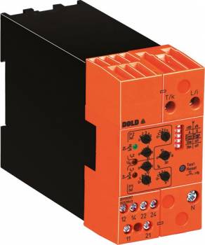
Dold 0059460 load monitor DC24V
| Lieske Part No. | 457600 |
|---|---|
| Mfg Part No | 0059460 |
| EAN-Code | 4030641594602 |
| Manufacturer | Dold |
| Here only | 512,29 EUR
609,63 EUR incl. VAT
|
Further information for Dold 0059460 load monitor DC24V
| Technical data | |
| 1- / 3-phase | 1, 3 |
| Enclosure design | Switch cabinet |
| Measuring range max. | 40 A (37 kW) |
| Output contacts | 2 x 1 C/O contacts |
| Width | 45 mm |
| Type | BH 9097 |
| Operate delay | |
| Variant | |
| Auxiliary voltage | DC 24 V |
| Contact equipping | 2 x 1 changeover contact |
| Nominal current max | AC 8 A |
| Nominal voltage | 3AC 60 - 440 V |
| Approvals and Markings | CCC |
| Variant | 3-phase with auxiliary supply. Start up delay time 0 - 30 s |
Applications
The load monitor is designed for monitoring industrial motors with variable loads. It is particularly suitable for applications where early detection of under- or overload conditions is critical to prevent damage to drives or connected machinery. Application areas include production plants, conveyor systems, pumps, and fans, where continuous operational reliability is required. The device can be used for both single-phase and three-phase loads, with the three-phase variant being the standard configuration.
Functions and Equipment in Detail
The device features two independent output relays, each with a single changeover contact, intended for signaling two different load conditions. The load monitoring thresholds (P1 and P2) are adjustable via rotary switches and are calibrated as absolute values in watts. Configuration is done via DIP switches, allowing the device to operate either as an under- and overload monitor (P1min/P2max) or as an overload monitor with a pre-warning stage (P1max/P2max). A common start-up bypass time ta (0 to 30 seconds) prevents false alarms during motor start-up. Operating states are indicated by two LEDs: a green LED for mains voltage and two yellow LEDs for the relay states P1 and P2. The LEDs flash during response delay or start-up bypass time and remain continuously lit when the respective relay is active.
Technology Explained Simply
Active power measurement is performed using a single-phase measurement principle, measuring the load in one phase and projecting it onto the total three-phase load. This requires symmetrical load distribution, which is typical for electric motors. Measurement is performed without external current transformers up to 40 A. The output relays can be switched between operating current principle (activated in fault condition) or rest current principle (not activated in fault condition), enabling flexible control of external switching devices. Configuration via DIP switches also controls memory behavior (automatic or manual). A test/reset button facilitates commissioning and serves as an adjustment aid.
Compatibility and Accessories
The device is designed for use in enclosures and complies with the standard IEC/EN 60255-1. It is designed for an auxiliary voltage of DC 24 V and can be used in industrial installations with corresponding supply voltage. The output relays are rated for a maximum switching voltage of 3AC 60 to 440 V and a nominal current of AC 8 A. The connection terminals are suitable for connecting with cables commonly used in industrial environments.
Mounting and Installation
Mounting is performed in an enclosure, with the width of 45 mm enabling standard mounting on DIN rails. The connection terminals are designed for connecting with electrical cables commonly used in industrial applications. Adjustment of load limits is done via rotary switches directly accessible on the device. Configuration of operating mode (operating or rest current principle, memory behavior) is done via DIP switches. Commissioning is facilitated by the test/reset button, which also serves as an adjustment aid.
Advantages in Operation
The load monitor enables early detection of load anomalies, allowing preventive maintenance and avoiding costly downtime. Adjustable thresholds and delay times offer flexibility in adapting to different systems. LED indicators provide clear signaling of operating status. Automatic range switching extends the measurement range without additional hardware. Configuration via DIP switches and rotary switches requires no special tools, simplifying commissioning and maintenance. The use of two independent relays allows differentiated responses to different load conditions, enhancing operational safety.

This is an offer of:
79279 Vörstetten
https://industry-electronics.com
Tel. 07666/88499-0
Fax. 07666/88499-111
Diesen Artikel finden Sie unter:
industry-electronics.com/artikel/457600

Lieske Elektronik e.K.
Reutener Str. 1079279 Vörstetten
https://industry-electronics.com
Tel. 07666/88499-0
Fax. 07666/88499-111
Diesen Artikel finden Sie unter:
industry-electronics.com/artikel/457600