
Dold 0059391 BH5904.02/00MF2/61 DC24V valve monitoring module
Industrial Material > Industrial relays and contactors > Switching units / measuring, control relay
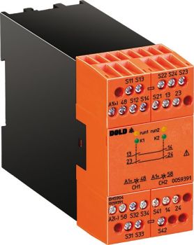
Dold 0059391 BH5904.02/00MF2/61 DC24V valve monitoring module
| Lieske Part No. | 900047 |
|---|---|
| Mfg Part No | 0059391 |
| EAN-Code | 4030641593919 |
| Manufacturer | Dold |
| Here only | 958,70 EUR
1.140,85 EUR incl. VAT
|
Further information for Dold 0059391 BH5904.02/00MF2/61 DC24V valve monitoring module
| Technical data | |
| Approvals | UL |
| Cat. / PL acc. to EN ISO 13849-1 | 4/e |
| Width | 45 mm |
| Type | BH 5904 |
| Variant | |
| Contact equipping | 2 NO contacts |
| Nominal voltage | DC 24 V |
| Approvals and Markings | UL-listed C/US, TÜV, UKCA |
Applications
The module is primarily intended for monitoring valve positions in hydraulic control systems, especially in press installations. It enables detection of valve status (open, closed) and responds to deviations from the specified position. The application is in safety-critical environments where a valve malfunction could lead to hazards. Integration into existing control systems is achieved via the integrated outputs and status messages.
Functions and Equipment in Detail
The device features 2 NO contacts as output contacts, which can be used to control downstream components such as warning lights, stop valves, or emergency stop switches. The outputs are designed as short-circuit, overload, and temperature-safe semiconductor outputs, ensuring high reliability and protection against faults in the connected circuit. The operating mode can be set: either monitoring of the valve per machine cycle or continuous monitoring. The type of valve signal to be monitored (2 NO, 2 NC, or 1 changeover) is also configurable. An integrated reset button allows error acknowledgment after fault detection.
Technology Explained Simply
The module monitors the position of the valve plunger by evaluating signals from valve status sensors. It detects wire breaks, short circuits, and crossed connections in the wiring circuit to avoid false alarms and ensure the integrity of the monitoring. Additionally, undervoltage and overvoltage detection is performed to enhance operational safety. The response time is a maximum of 28 ms, enabling rapid reaction to disturbances. Operating states are visually indicated via LED displays (Run 1, Run 2). Power supply is via DC 24 V, which is a standard voltage in industrial electrical engineering.
Compatibility and Accessories
The device is designed for use with standard hydraulic blocks in press installations. The contact configuration allows control of external relays for contact amplification if required. The certifications UL-listed C/US, TÜV, UKCA and compliance with EN ISO 13849-1 (Category 4, Performance Level e) and IEC/EN 62061 (SIL CL 3) guarantee suitability for safety-critical applications. The safety integrity also corresponds to SIL 3 according to IEC/EN 61508.
Mounting and Installation
The module is mounted in standard control panels with a width of 45 mm. The connection terminals are intended for connecting to valve status sensors and downstream safety components. Installation is carried out according to the manufacturer’s technical instructions, with correct wiring and compliance with safety regulations being essential. The operating mode and valve signal type are configured via device settings.
Advantages in Operation
The integrated fault detection (wire break, short circuit, voltage failure) increases the reliability of monitoring. The fast response time of 28 ms enables timely reaction to disturbances. Visual indication of operating states facilitates diagnosis and maintenance. Configurability of operating mode and valve signal type offers flexibility when integrating into various plant concepts. The certifications and safety qualifications ensure compliance with applicable standards in safety-critical applications.

This is an offer of:
79279 Vörstetten
https://industry-electronics.com
Tel. 07666/88499-0
Fax. 07666/88499-111
Diesen Artikel finden Sie unter:
industry-electronics.com/artikel/900047

Lieske Elektronik e.K.
Reutener Str. 1079279 Vörstetten
https://industry-electronics.com
Tel. 07666/88499-0
Fax. 07666/88499-111
Diesen Artikel finden Sie unter:
industry-electronics.com/artikel/900047