
Dold 0059191 load monitor AC230/110V
Industrial Material > Industrial relays and contactors > Switching units / measuring, control relay
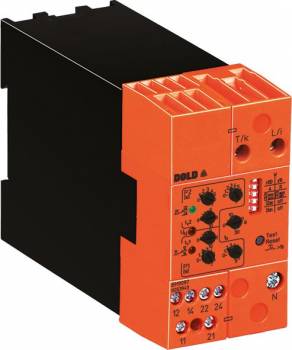
Dold 0059191 load monitor AC230/110V
| Lieske Part No. | 690842 |
|---|---|
| Mfg Part No | 0059191 |
| EAN-Code | 4030641591915 |
| Manufacturer | Dold |
| Here only | 512,29 EUR
609,63 EUR incl. VAT
|
Further information for Dold 0059191 load monitor AC230/110V
| Technical data | |
| 1- / 3-phase | 1, 3 |
| Enclosure design | Switch cabinet |
| Measuring range max. | 40 A (37 kW) |
| Output contacts | 2 x 1 C/O contacts |
| Width | 45 mm |
| Type | BH 9097 |
| Operate delay | |
| Variant | |
| Auxiliary voltage | AC 230/110 V |
| Contact equipping | 2 x 1 changeover contact |
| Nominal current max | AC 8 A |
| Nominal voltage | 3AC 60 - 440 V |
| Approvals and Markings | CCC |
| Variant | 3-phase with auxiliary supply. Start up delay time 0 - 30 s |
Applications
The load monitor is designed for monitoring electrical industrial motors with variable loads. It can be used in both single-phase and three-phase systems, with three-phase systems requiring symmetrical phase loading, as is typical for motor loads. The maximum monitorable load is 40 A, corresponding to a power of 37 kW at 690 V. The device is also suitable for motors up to 22 kW at 400 V. Applications are in industrial environments, where preventive maintenance and early fault detection contribute to avoiding failures and damage.
Functions and Equipment in Detail
The device features two independent output relays, each with a 1-changeover contact, for signaling underload (P1) and overload (P2). The threshold values for P1 and P2 can be set via rotary switches as absolute values in watts. Configuration is done via DIP switches, allowing the device to operate either as an under- and overload monitor (P1min/P2max) or as an overload monitor with a warning stage (P1max/P2max). The relays can be switched between operating current principle (activated in fault condition) and rest current principle (not activated in fault condition). Two LEDs indicate the relay status: a green LED indicates mains voltage, while two yellow LEDs show the status of relays P1 and P2. The LEDs flash during response delay or during setting assistance, and remain lit continuously when the respective relay is active.
Technology Explained Simply
Measurement is performed based on the principle of active power measurement. The device measures the actual electrical power consumed by the motor and compares it with the set threshold values. If these values are exceeded or undershot, the corresponding relay is activated. A common start-up bypass time ta (0–30 seconds) prevents false triggering during motor start-up. Automatic range switching enables a wide current measurement range up to 40 A without external current transformers. Device configuration is done via DIP switches, which also control the reset behavior (automatic or manual reset).
Compatibility and Accessories
The device is designed for an auxiliary voltage of AC 230/110 V and can be mounted in enclosures with a width of 45 mm. It is designed for nominal voltages of 3AC 60–440 V and a maximum nominal current of AC 8 A. The CCC certification is specified. The device is used in industrial plants, where operational safety and drive availability are prioritized.
Mounting and Installation
Mounting is done in an enclosure, where the width of 45 mm determines the mounting height. Connections are made via the designated terminals, with care taken to correctly connect the current terminals to avoid negative load measurement (reverse power). The threshold values and delay times are set via rotary switches and DIP switches. A test/reset button facilitates commissioning and serves as a setting aid. The LED indicators support diagnosis and status monitoring during operation.
Advantages in Operation
By detecting load anomalies such as under- or overload at an early stage, the load monitor enables preventive maintenance and reduces the risk of machine failures. The clear signaling via LEDs and the flexible configuration of relay functions (operating or rest current principle) offer flexibility when integrating into existing control systems. Reduced wiring and easy commissioning via the test/reset button reduce installation effort. Compliance with the standard IEC/EN 60255-1 ensures reliability and safety of the device in industrial applications. Operational safety is enhanced through continuous monitoring and precise response to load deviations.

This is an offer of:
79279 Vörstetten
https://industry-electronics.com
Tel. 07666/88499-0
Fax. 07666/88499-111
Diesen Artikel finden Sie unter:
industry-electronics.com/artikel/690842

Lieske Elektronik e.K.
Reutener Str. 1079279 Vörstetten
https://industry-electronics.com
Tel. 07666/88499-0
Fax. 07666/88499-111
Diesen Artikel finden Sie unter:
industry-electronics.com/artikel/690842