
Dold 0058785 SN7920 time relay AC/DC24-230V
Industrial Material > Industrial relays and contactors > Industrial Timers
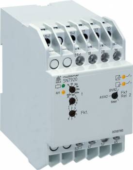
Dold 0058785 SN7920 time relay AC/DC24-230V
| Lieske Part No. | 1439876 |
|---|---|
| Mfg Part No | 0058785 |
| EAN-Code | 4030641587857 |
| Manufacturer | Dold |
| Here only | 304,95 EUR
362,89 EUR incl. VAT
|
Further information for Dold 0058785 SN7920 time relay AC/DC24-230V
| Technical data | |
| Enclosure design | Switch cabinet |
| Output contacts | 2 NC contacts, 4 NO contacts |
| Time function(s) | Flasher relay, Fleeting on break, Fleeting on make, Impulsgeber, Off-delay, with control signal, On- and Off-delay, On-delay, Pulse extender |
| Width | 52,5 mm |
| Type | SN 7920 |
| Variant | |
| Contact equipping | 2 x 2 NO contacts, 2 NC contacts |
| Nominal voltage | AC/DC 24 - 230 V |
| Time range | 0,05 s - 300 h |
| Approvals and Markings | UKCA |
| Variant | To switch high DC-loads with mechanical forcibly guided contacts |
Applications
This relay is used in industrial control systems where time-controlled sequences are required, for example in automation technology, plant control systems, or railway systems. The versatility of its functions allows integration into various control logics without additional components. Its high DC switching capacity makes it suitable for applications with high current loads.
Functions and Equipment in Detail
The device offers eight different time functions, selectable via a rotary switch: delay-on (AV), make-before-break function (EW), delayed pulse generator (IE), blink function with pulse start (BI), delay-off (RV), pulse shaper (IF), break-before-make function (AW), and delay-on/delay-off (AV/RV). The time functions are adjustable via a rotary switch, with settings taking effect only when the auxiliary voltage is switched on. The time ranges are adjustable in eight steps from 0.05 s to 300 h via another rotary switch. An adjustment aid enables quick and precise setting of long times, with the LED flash frequency serving as a reference.
Technology Explained Simply
The relay features two relay stages. Relay 1 is configured as a timer and provides 1 normally open contact and 2 normally closed contacts. Relay 2 can be switched between three operating modes via a rotary switch: as a timer (in parallel with Relay 1), as an immediate contact via auxiliary voltage A1/A2, or as an immediate contact via control input B1/B2. The contacts are mechanically forced-guided, ensuring secure and reliable switching even under high DC loads. LED indicators signal the operating voltage (green LED), the state of the output relay, and the timing process (yellow LED). The yellow LED displays continuous light, flashing light, or off depending on the operating state, providing visual status indication.
Compatibility and Accessories
The relay is designed for mounting on a DIN rail or via screw mounting. It is rated for operating voltages in the range AC/DC 24 to 230 V. The functions are adjustable via rotary switches, with settings taking effect only when the auxiliary voltage is switched on. The time functions can be combined with time interruption or time addition, increasing flexibility in complex control systems.
Mounting and Installation
Mounting is either on a DIN rail or via screw mounting. The width of 52.5 mm allows installation in standard enclosures. The terminal connections are clearly labeled: A1(+) / A2 for auxiliary voltage, B1(+) / B2 for control input, and contacts 17, 18, 27, 28, 35, 36, 15, 16, 47, 48, 57, 58, 65, 66, 33, 34, 43, 44, 31, 32 for relay outputs. Functions and time ranges are adjusted via rotary switches, with settings taking effect only when the auxiliary voltage is switched on.
Advantages in Operation
By combining eight functions in one device, the number of required components is reduced. The mechanically forced-guided contacts ensure high reliability when switching high DC loads. The LED indicators allow for quick visual inspection of the operating status. The adjustment aid for long times simplifies calibration, especially for long time intervals. Support for time addition and time interruption expands application possibilities in complex control systems. The mounting options (DIN rail/screw mounting) increase flexibility during installation in existing enclosures.

This is an offer of:
79279 Vörstetten
https://industry-electronics.com
Tel. 07666/88499-0
Fax. 07666/88499-111
Diesen Artikel finden Sie unter:
industry-electronics.com/artikel/1439876

Lieske Elektronik e.K.
Reutener Str. 1079279 Vörstetten
https://industry-electronics.com
Tel. 07666/88499-0
Fax. 07666/88499-111
Diesen Artikel finden Sie unter:
industry-electronics.com/artikel/1439876