
Dold 0057302 brake device BI9023 UH AC400V 60A
Industrial Material > Engines and accessories
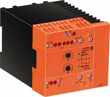
Dold 0057302 brake device BI9023 UH AC400V 60A
| Lieske Part No. | 514766 |
|---|---|
| Mfg Part No | 0057302 |
| EAN-Code | 4030641573027 |
| Manufacturer | Dold |
| Here only | 508,14 EUR
604,69 EUR incl. VAT
|
Further information for Dold 0057302 brake device BI9023 UH AC400V 60A
| Technical data | |
| Braking current adjustable up to max. | 80 A |
| Braking time adjustable up to max. | 20 s |
| Width | 90 mm |
| Type | BI 9023 |
| External brake contactor required | |
| Signalling output | |
| Temperature monitoring | |
| Variant | |
| Auxiliary voltage | AC 400 V |
| Braking current | 60 A |
| Braking time | 1 - 20 s |
| Contact equipping | 2 NO contacts |
| Nominal voltage | 2AC 200 - 480 V |
| Approvals and Markings | UKCA |
| Variant | Adjustable braking time 1 ... 20 s |
Applications
This device is suitable for all asynchronous motors and is particularly used in machines where rapid and safe braking is required. Typical application areas include sawmills, centrifuges, woodworking machines, textile machines, and conveyor systems. The simple mounting allows installation in existing systems without extensive modifications.
Functions and Equipment in Detail
The brake device features an adjustable braking time from 1 to 20 seconds, which can be adapted to specific applications. The braking current is adjustable up to 80 A, with the specified value being 60 A. The rated voltage is 2AC 200 to 480 V, and the auxiliary voltage is AC 400 V. The contact configuration includes two normally open contacts (2 NO contacts), used for controlling the external brake contactor. An integrated alarm output indicates the operating status, and a temperature monitoring system protects the device from overheating.
Technology Explained Simply
Braking is achieved through phase-cut control, whereby the braking current is applied to the motor windings via terminals T1 and T2. The safety time of 750 ms ensures that the motor contactor is fully de-energized before the braking current flows, preventing induced voltages. After the set braking time has elapsed, the current is switched off, and the device is ready for restart after a reset time of 350 ms. The green LED indicates that the auxiliary voltage is present, while the yellow LEDs indicate the status of relays K1 and K2. A fault code is indicated by flashing LED signals, with the number of flashes indicating the fault code (e.g., 4 for missing voltage L1-L2).
Compatibility and Accessories
It is designed for use with asynchronous motors and can be integrated into existing control systems. The width is 90 mm, enabling compact mounting on the standard rail. The UKCA approval is specified, allowing use in relevant markets.
Mounting and Installation
The device is mounted on a 35 mm standard rail. The connection terminals L1-L2 are for the supply voltage of the braking system, while terminals A1-A2 receive the auxiliary voltage (AC 400 V). The interlock contact Q1-Q2 is connected to the motor contactor. Installation must follow the instructions in the datasheet, ensuring correct wiring and compliance with safety regulations.
Operational Advantages
The device is wear-free and maintenance-free, reducing operating costs and increasing availability. The adjustable parameters of braking current and braking time allow adaptation to different motors and applications. The integrated temperature monitoring and fault indication ensure high operational safety. The simple mounting and integration into existing systems reduce installation effort.

This is an offer of:
79279 Vörstetten
https://industry-electronics.com
Tel. 07666/88499-0
Fax. 07666/88499-111
Diesen Artikel finden Sie unter:
industry-electronics.com/artikel/514766

Lieske Elektronik e.K.
Reutener Str. 1079279 Vörstetten
https://industry-electronics.com
Tel. 07666/88499-0
Fax. 07666/88499-111
Diesen Artikel finden Sie unter:
industry-electronics.com/artikel/514766