
Dold 0056040 time relay delayed return
Industrial Material > Industrial relays and contactors > Industrial Relays
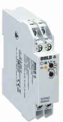
Dold 0056040 time relay delayed return
| Lieske Part No. | 1312968 |
|---|---|
| Mfg Part No | 0056040 |
| EAN-Code | 4030641560409 |
| Manufacturer | Dold |
| Here only | 117,80 EUR
140,18 EUR incl. VAT
|
Further information for Dold 0056040 time relay delayed return
| Technical data | |
| Enclosure design | Switch cabinet |
| Output contacts | 1 C/O contact |
| Time function(s) | Off-delay, with control signal |
| Width | 17,5 mm |
| Type | SK 9962 |
| Connection facility for remote potentiometer | |
| Variant | |
| Contact equipping | 1 changeover contact |
| Nominal voltage | AC/DC 12 - 240 V |
| Time range | 0,05 s - 300 h |
| Approvals and Markings | UKCA |
| Variant | Release delay, with control signal |
Applications
This relay is suitable for applications requiring time-delayed deactivation, for example in motor control, lighting systems, or safety functions in production plants. The drop-out delay allows the output to remain active for a defined period even after the control signal has been switched off. This is particularly useful in processes where immediate deactivation could cause disturbances or damage.
Functions and Equipment in Detail
The device features a changeover contact as the output contact, suitable for controlling loads. The time delay is adjustable via a rotary switch in eight time ranges from 0.05 seconds to 300 hours. An adjustment aid enables quick and precise setting of long times by using the blinking frequency of the yellow LED (1 second ± 4%) as a reference. The yellow LED indicates the operating status: steady light means the output relay is activated, flashing light indicates the timing process. A green LED indicates that the auxiliary voltage is present.
Technology Explained Simply
The time function is activated by a control signal input (B1), which is potential-referenced to A2. The auxiliary voltage must be continuously applied to A1/A2. The device does not require a potential-free control contact, simplifying installation. The time delay is implemented by an internal timer programmed via the rotary switch. Adjustment is made directly on the device; changing the setting during timing may cause unintended switching operations.
Compatibility and Accessories
The relay features a connection option for a remote potentiometer (10 kΩ), connected via terminals Z1-Z2. This enables remote fine adjustment of the timing, with the rotary knob on the device set to minimum. The remote potentiometer wiring should be routed separately from AC mains voltage lines; if routed together, shielded cable is recommended, with the shield connected to Z1. Terminals Z1-Z2 are not galvanically isolated from A1/A2, so no foreign voltage potentials may be connected.
Mounting and Installation
The device is designed for installation in enclosures, with a depth of 98 mm. The terminals are located at the top, facilitating installation on mounting plates and in cable ducts. Installation is carried out in the usual manner in enclosures with mounting plate. Terminal designations are clearly defined: A1/A2 for auxiliary voltage, B1 for control input, 15-16-18 for the changeover contact.
Operational Advantages
The combination of a wide voltage range, eight adjustable time ranges, and the possibility of remote control via a remote potentiometer makes the device highly flexible. The LED indicators simplify diagnosis and maintenance, as the operating status is visually recognizable. The adjustment aid for long times reduces setup time and increases accuracy. The enclosure-compatible design and compact width of 17.5 mm enable efficient space utilization in electrical control systems.
Approvals and Markings
The device bears the UKCA mark, confirming compliance with applicable European safety and operational requirements. Manufacturing is carried out in accordance with the requirements of standard EN 61812-1, which applies to time relays.
Enclosure Design
The housing is designed for use in enclosures, with terminals located at the top. The SK 9962 design is specifically intended for enclosures with mounting plate and cable duct.
Time Function
The time function is drop-out delayed with control signal, meaning the output contact remains active for the set time after the control signal is switched off.
Remote Potentiometer Connection
The connection option for a remote potentiometer (10 kΩ) via terminals Z1-Z2 enables remote fine adjustment of the timing. Terminals Z1-Z2 are not galvanically isolated from A1/A2, so no foreign voltage potentials may be connected.
LED Indicators
The green LED indicates that the auxiliary voltage is present. The yellow LED indicates the operating status: steady light means the output relay is activated, flashing light indicates the timing process.
Control Input
The control input B1 is operated with voltage relative to A2. The control voltage can be in the range AC/DC 12 to 240 V and does not need to match the auxiliary voltage. A parallel load resistor (e.g. a contactor) between B1 and A2 is permissible.
Adjustment Aid
The adjustment aid uses the blinking frequency of the yellow LED (1 second ± 4%) as a reference to quickly and precisely set long times. The multiplication factors between time ranges are exact, making the adjustment aid particularly useful.
Width
The width is 17.5 mm, enabling compact installation in enclosures.
Enclosure Design
The device is designed for use in enclosures, with terminals located at the top. The SK 9962 design is specifically intended for enclosures with mounting plate and cable duct.
Time Function
The time function is drop-out delayed with control signal, meaning the output contact remains active for the set time after the control signal is switched off.
Remote Potentiometer Connection
The connection option for a remote potentiometer (10 kΩ) via terminals Z1-Z2 enables remote fine adjustment of the timing. Terminals Z1-Z2 are not galvanically isolated from A1/A2, so no foreign voltage potentials may be connected.
LED Indicators
The green LED indicates that the auxiliary voltage is present. The yellow LED indicates the operating status: steady light means the output relay is activated, flashing light indicates the timing process.
Control Input
The control input B1 is operated with voltage relative to A2. The control voltage can be in the range AC/DC 12 to 240 V and does not need to match the auxiliary voltage. A parallel load resistor (e.g. a contactor) between B1 and A2 is permissible.
Adjustment Aid
The adjustment aid uses the blinking frequency of the yellow LED (1 second ± 4%) as a reference to quickly and precisely set long times. The multiplication factors between time ranges are exact, making the adjustment aid particularly useful.
Width
The width is 17.5 mm, enabling compact installation in enclosures.

This is an offer of:
79279 Vörstetten
https://industry-electronics.com
Tel. 07666/88499-0
Fax. 07666/88499-111
Diesen Artikel finden Sie unter:
industry-electronics.com/artikel/1312968

Lieske Elektronik e.K.
Reutener Str. 1079279 Vörstetten
https://industry-electronics.com
Tel. 07666/88499-0
Fax. 07666/88499-111
Diesen Artikel finden Sie unter:
industry-electronics.com/artikel/1312968