
Dold 0055291 undervoltage relay 3/N AC400/230V 0,75UN
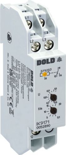
Dold 0055291 undervoltage relay 3/N AC400/230V 0,75UN
| Lieske Part No. | 1153830 |
|---|---|
| Mfg Part No | 0055291 |
| EAN-Code | 4030641552916 |
| Manufacturer | Dold |
| Here only | 114,68 EUR
136,47 EUR incl. VAT
|
Further information for Dold 0055291 undervoltage relay 3/N AC400/230V 0,75UN
| Technical data | |
| 1- / 3-phase | 1, 3 |
| Auxiliary voltage | Without |
| Enclosure design | Distribution board |
| Nominal voltage max. | 3/N AC 500 / 290 V |
| Output contacts | 1 C/O contact |
| Width | 17,5 mm |
| Type | IK 9171 |
| Operate delay | |
| Variant | |
| Contact equipping | 1 changeover contact |
| Nominal voltage | 3/N AC 400 / 230 V |
| Response value | 0,75 Un |
| Time delay | 5 - 15 min |
| Approvals and Markings | UKCA |
| Variant | With N. NC circuit operation. Settable time delay t2. Fixed response value |
Applications
The relay is used for network monitoring, particularly in the field of safety power supply and safety lighting in accordance with DIN VDE 0100-710 and DIN VDE 0108. It is suitable for applications requiring automatic switching to a backup supply in the event of a voltage dip. The application is independent of phase sequence, enabling flexible installation. The device variant with time delay t2 is especially suitable for networks with local power generation or in regions with unstable power supplies, where a staged restart of consumers is necessary.
Functions and Equipment in Detail
The device features an output contact in the form of a changeover contact (1 changeover contact), which can be used to control auxiliary consumers or switching devices. The contact status is indicated by a yellow LED, which lights up when the output relay contact is closed (contacts 11-14). Measurement is performed using the arithmetic mean of the individual phases against the neutral conductor. For variants without neutral conductor connection, L1 and L3 are measured against L2 (IK/SK 9171) or L1 and L2 against L3 (IL/SL 9171). In single-phase operation, terminals L1, L2, and L3 must be bridged. The time delay t1 is only effective if the phase voltage L1-N (IK/SK 9171) or L3-N (IL/SL 9171) is at least 0.5 Un. Upon switching on the operating voltage, the device initially enters the normal state, even if a fault is present; the fault state is only activated after the time delay t1 has elapsed.
Technology Explained Simply
The relay continuously monitors the voltage in the network and responds when the defined pickup value of 0.75 Un is undershot. The time delay t2 ensures that after voltage restoration, not all consumers are switched back on immediately, but only after a defined waiting period. This prevents inrush currents and protects sensitive equipment. The hysteresis is approximately 4%, meaning the device only returns to the normal state when the voltage rises above the pickup value by 4%. The frequency range coverage is between 45 and 65 Hz, enabling use in various networks. The device requires no auxiliary voltage, simplifying installation and increasing reliability.
Compatibility and Accessories
The relay is designed for use in installation and industrial distributors in accordance with DIN 43 880. Type I (IK 9171) has a depth of 59 mm and bottom-mounted connection terminals. The width is 17.5 mm. It is compatible with various network voltages and can be used in both 3-phase and single-phase systems. The device variant is certified to IEC/EN 60255-1 and carries the UKCA mark.
Mounting and Installation
Mounting is carried out in installation or industrial distributors in accordance with DIN 43 880. The connection terminals are located at the bottom, enabling easy integration into existing switchgear. The width of 17.5 mm allows for compact placement. The terminals are designed for connection to cables, with the exact connection method shown in the device’s wiring diagram. Installation requires no additional tools, as the device operates without auxiliary voltage.
Operational Advantages
The relay provides reliable network monitoring without requiring additional power supply. The adjustable time delay t2 enables targeted control of consumer restart, increasing the lifespan of equipment. The LED indicator provides visual feedback on the operating status. Independence from phase sequence and compatibility with various network voltages increase installation flexibility. Certification to IEC/EN 60255-1 and the UKCA mark guarantee compliance with relevant safety and quality standards.

This is an offer of:
79279 Vörstetten
https://industry-electronics.com
Tel. 07666/88499-0
Fax. 07666/88499-111
Diesen Artikel finden Sie unter:
industry-electronics.com/artikel/1153830

Lieske Elektronik e.K.
Reutener Str. 1079279 Vörstetten
https://industry-electronics.com
Tel. 07666/88499-0
Fax. 07666/88499-111
Diesen Artikel finden Sie unter:
industry-electronics.com/artikel/1153830