
Dold 0054362 IK7854.81AC/DC12-240V0,05S-300H timer
Industrial Material > Industrial relays and contactors > Industrial Timers
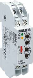
Dold 0054362 IK7854.81AC/DC12-240V0,05S-300H timer
| Lieske Part No. | 925384 |
|---|---|
| Mfg Part No | 0054362 |
| EAN-Code | 4030641543624 |
| Manufacturer | Dold |
| Here only | 166,36 EUR
197,97 EUR incl. VAT
|
Further information for Dold 0054362 IK7854.81AC/DC12-240V0,05S-300H timer
| Technical data | |
| Enclosure design | Distribution board |
| Time function(s) | Cyclic timer |
| Width | 17,5 mm |
| Type | IK 7854 |
| Connection facility for remote potentiometer | |
| Variant | |
| Contact equipping | 1 changeover contact delayed |
| Nominal voltage | AC/DC 12 - 240 V |
| Time range | 0,05 s - 300 h |
| Approvals and Markings | UKCA |
| Variant | Selectable start with impulse or break |
Applications
This relay is designed for use in installation and industrial distributors in accordance with DIN 43880. It is particularly suitable for applications requiring precise, time-controlled switching sequences, such as in manufacturing automation, building automation, or warning and signaling systems. The ability to start operation with either a pulse or a pause expands its application possibilities in complex control sequences.
Functions and Equipment in Detail
The device features 8 adjustable time ranges, covered by a rotary switch from 0.05 seconds up to 300 hours. The pulse and pause times are independently adjustable, allowing flexible adaptation to different requirements. Adjustment is performed via a rotary switch, with an adjustment aid integrated for quick setting of long durations. The period duration of the yellow LED is 1 second ± 4 % and serves as a reference for precise time adjustment, especially for long delay times.
Technology Explained Simply
The relay operates according to the standard IEC/EN 61812-1 and is designed as an asymmetric flash relay, meaning that the pulse and pause times can be of different lengths. The operating voltage is supplied via terminals A1/A2, and control is also possible via two-wire proximity switches. For operating voltages above 24 V and when using proximity switches without built-in short-circuit protection, it is recommended to install a series resistor in the supply line to A1 to limit the inrush current. The size of the series resistor depends on the operating voltage and the maximum switching current of the proximity switch.
Compatibility and Accessories
The device includes a connection option for two remote potentiometers (10 kΩ), enabling external, remotely controlled fine adjustment of timing. This option is particularly useful in systems where direct access to the relay is not possible or desired. Compatibility with two-wire proximity switches (AC or DC) extends its application possibilities in various control systems.
Mounting and Installation
The relay is mounted in an installation distributor and is suitable for installation in enclosures with mounting plate and cable duct. The terminals are located at the bottom, enabling easy integration into existing distributors. The depth of 59 mm and width of 17.5 mm conform to common standards for modular components in electrical installations.
Advantages in Operation
The LED indicators signal operational readiness (green LED) as well as the state of the output relay and the timing process (yellow LED “R/t”). The yellow LED blinks in different patterns depending on whether the output relay is activated (long on, short off) or not (short on, long off), enabling quick visual inspection of the operating status. The ability to start operation with either a pulse or a pause provides additional flexibility in control logic. The UKCA certification confirms compliance with applicable European safety and quality requirements.

This is an offer of:
79279 Vörstetten
https://industry-electronics.com
Tel. 07666/88499-0
Fax. 07666/88499-111
Diesen Artikel finden Sie unter:
industry-electronics.com/artikel/925384

Lieske Elektronik e.K.
Reutener Str. 1079279 Vörstetten
https://industry-electronics.com
Tel. 07666/88499-0
Fax. 07666/88499-111
Diesen Artikel finden Sie unter:
industry-electronics.com/artikel/925384