
Dold 0053802 insulation monitor DC12-280V UH AC220-240V
Industrial Material > Industrial relays and contactors > Switching units / measuring, control relay
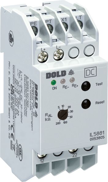
Dold 0053802 insulation monitor DC12-280V UH AC220-240V
| Lieske Part No. | 1312950 |
|---|---|
| Mfg Part No | 0053802 |
| EAN-Code | 4030641538026 |
| Manufacturer | Dold |
| Here only | 266,06 EUR
316,61 EUR incl. VAT
|
Further information for Dold 0053802 insulation monitor DC12-280V UH AC220-240V
| Technical data | |
| Enclosure design | Distribution board |
| IMD type | DC |
| Nominal voltage IT system | DC 12 - 280 V, DC 24 - 500 V |
| Response value | 5 - 500 kΩ |
| Response value type | Adjustable |
| Width | 35 mm |
| Type | IL 5881 |
| Earth fault indicator | |
| Variant | |
| Alarm value | 5 - 200 kOhm |
| Auxiliary voltage | AC 220 - 240 V |
| Contact equipping | 2 changeover contacts |
| Nominal voltage | DC 12 - 280 V |
| Time delay | without |
| Approvals and Markings | UKCA, CCC |
Applications
The IL5881.12 is used for continuous monitoring of IT systems in industrial plants, particularly in areas where interruption of power supply is not acceptable. Applications also include railway systems, where the reliability of electrical systems is of high importance. The device detects earth faults in the network and signals them via optical indication, enabling quick fault localization.
Functions and Equipment in Detail
The device features two changeover contacts as contact configuration, which interrupt the output current when an earth fault is detected. The trip thresholds are adjustable via a potentiometer on the front of the device, with the alarm threshold ranging from 5 to 200 kΩ. Indication is provided via LEDs: a green LED indicates operational status, while red LEDs light up for earth faults on L+ or L-. Selective earth fault detection allows identification of whether the fault occurs on the positive or negative line.
Technology Explained Simply
The isolation monitor operates on the principle of residual current, where the output relay de-energizes in the event of a fault rather than being activated. The trip threshold is adjusted via a potentiometer, allowing the operator to adapt the alarm threshold to the specific requirements of the installation. The function can be programmed to operate in memory or hysteresis mode. In hysteresis mode, the device automatically resets when the insulation resistance rises above the set value again. In memory mode, the fault condition remains stored until reset via the internal or external reset button.
Compatibility and Accessories
The device is designed for IT systems with a nominal voltage of DC 12 to 280 V. On request, variants with a measurement range up to DC 500 V and a separate auxiliary voltage are available. The connection terminals are designed for mounting in installation distributors, with a depth of 61 mm. External test and reset buttons can be connected to extend functionality.
Mounting and Installation
Mounting is either on a DIN rail or via screw fastening. The width of 35 mm allows for compact installation in standard distributors. The connection terminals are located at the bottom, facilitating integration into installation distributors according to DIN 43880. The auxiliary voltage is drawn directly from the monitored network, eliminating the need for additional power supply.
Operational Advantages
The IL5881.12 provides preventive protection against fires and equipment damage through early detection of insulation faults. The simple adjustment of the trip threshold and selective fault indication enable quick diagnosis and maintenance. Integrated test and reset buttons, along with the option to connect external buttons, increase operational flexibility. Compliance with standard IEC/EN 61557-8 ensures standardized functionality.
Approvals and Markings
The device carries the UKCA and CCC approvals, confirming compliance with applicable safety and quality requirements in the respective markets. Compliance with standard IEC/EN 61557-8 ensures the reliability of measurement and alarm functions.
Components and Operating States
Operating states are indicated via LEDs: green LED for operational readiness, red LEDs for earth fault on L+ or L-. The test and reset functions are available via integrated buttons and external connections. Programming of the behavior (memory or hysteresis mode) is done via a bridge between terminals LT and X1.
Function Explanation
When the set alarm threshold R_AL is undershot, the corresponding red LED (RE+ or RE-) lights up, and the output relay de-energizes. In hysteresis mode (bridge LT-X1), the device automatically resets when the insulation resistance rises again. Without the bridge, the fault condition remains stored until reset via the reset button. The test button simulates an earth fault to test functionality.
Application Scenarios
The device is particularly suitable for installations where interruption of power supply is unacceptable, such as in industrial production plants, medical facilities, or railway systems. Continuous monitoring of insulation resistance enables proactive maintenance and prevents potential damage from insulation faults.

This is an offer of:
79279 Vörstetten
https://industry-electronics.com
Tel. 07666/88499-0
Fax. 07666/88499-111
Diesen Artikel finden Sie unter:
industry-electronics.com/artikel/1312950

Lieske Elektronik e.K.
Reutener Str. 1079279 Vörstetten
https://industry-electronics.com
Tel. 07666/88499-0
Fax. 07666/88499-111
Diesen Artikel finden Sie unter:
industry-electronics.com/artikel/1312950