
Dold 0053378 insulation monitor 220-240V
Industrial Material > Industrial relays and contactors > Switching units / measuring, control relay
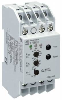
Dold 0053378 insulation monitor 220-240V
| Lieske Part No. | 799159 |
|---|---|
| Mfg Part No | 0053378 |
| EAN-Code | 4030641533786 |
| Manufacturer | Dold |
| Here only | 251,89 EUR
299,75 EUR incl. VAT
|
Further information for Dold 0053378 insulation monitor 220-240V
| Technical data | |
| Enclosure design | Distribution board |
| IMD type | AC |
| Nominal voltage IT system | AC 0 - 500 V |
| Response value | 5 - 500 kΩ |
| Response value type | Adjustable |
| Width | 35 mm |
| Type | IL 5880 |
| Earth fault indicator | |
| Variant | |
| Alarm value | 5 - 100 kOhm |
| Auxiliary voltage | AC 220 - 240 V 50 - 400 Hz |
| Contact equipping | 2 changeover contacts |
| Prewarning value | Without |
| Approvals and Markings | UKCA, CCC |
| Variant | Adjustable alarm value. De-energized on trip |
Applications
The insulation monitor is intended for pure alternating and rotating current networks with a voltage of 0 to 500 V and a frequency of 10 to 10000 Hz. It is particularly suitable for industrial and railway applications, as well as for monitoring de-energized consumers, for example, motor windings of devices that must be switched on in an emergency. The separate supply voltage enables monitoring even when the network is de-energized, which is important for mobile power generators or emergency power systems.
Functions and Equipment in Detail
The device features two changeover contacts as contact configuration, used for signal input into monitoring systems. The trip threshold for earth fault is adjustable and can be set via a potentiometer on the front of the device between 5 and 100 kΩ. The operational status is indicated by LEDs: a green LED indicates readiness for operation, while a red LED signals an insulation fault. The function of the output relays is programmable, allowing selection between memory and hysteresis behavior. The reset and test button on the device enables manual reset and testing of the status. Additionally, external reset and test buttons can be connected.
Technology Explained Simply
The insulation monitor monitors the resistance between the electrical network and earth. If the insulation resistance falls below the set alarm threshold of 5 to 100 kΩ, a fault is signaled. The galvanic isolation between the measurement circuit, auxiliary voltage, and output contacts ensures safe and interference-free measurement. The trip threshold setting is done via a potentiometer, making adaptation to different requirements simple and user-friendly. The LED indicators provide visual feedback on the operational status, enabling quick diagnosis.
Compatibility and Accessories
The device is specified according to IEC/EN 61557-8 and meets the requirements for monitoring IT systems. It is suitable for mounting in enclosures with mounting plates and cable ducts, as well as in installation distributors. Mounting is done either on DIN rails or by screws. The variant IL5880.12AC50-400HZ220-240V is supplied without a pre-warning threshold. Other variants of the series, such as IL/SL 5880/300, are available for mobile power generators according to DIN VDE 0100-551, but are not part of this version.
Mounting and Installation
Mounting is done in standard installation distributors with a depth of 61 mm and bottom-mounted connection terminals. The connection terminals are intended for connection to the monitored IT system, the protective conductor, and for external test and reset buttons. The DIN rail or screw mounting allows flexible integration into existing switchgear. The connection designations are described in detail in the data sheet.
Advantages in Operation
The insulation monitor provides preventive fire and system protection through early detection of insulation faults. The simple adjustment of the trip threshold and visual indication via LEDs simplify maintenance and diagnosis. The ability to monitor de-energized systems extends the application range in emergency power and mobile installations. The programmable function of the output relays allows flexible adaptation to different operational requirements.
Approvals and Markings
The device carries the UKCA and CCC approvals, confirming compliance with applicable safety and quality standards. Compliance with the standard IEC/EN 61557-8 ensures reliability and functionality in industrial use.
Functions and Features
The device is designed for monitoring IT systems with a nominal voltage of AC 0 to 500 V. The auxiliary voltage is AC 220 to 240 V at 50 to 400 Hz. The contact configuration includes two changeover contacts. The trip threshold is adjustable and ranges from 5 to 100 kΩ. Indication is provided via LEDs for operational readiness (green) and insulation fault (red). The function of the output relays is programmable, allowing selection between memory and hysteresis behavior. Mounting is in installation distributors with a width of 35 mm. Galvanic isolation between the measurement circuit, auxiliary voltage, and output contacts ensures safe measurement. The reset and test button enables manual reset and testing. External reset and test buttons can be connected. The device has UKCA and CCC approvals. The standard IEC/EN 61557-8 is complied with.

This is an offer of:
79279 Vörstetten
https://industry-electronics.com
Tel. 07666/88499-0
Fax. 07666/88499-111
Diesen Artikel finden Sie unter:
industry-electronics.com/artikel/799159

Lieske Elektronik e.K.
Reutener Str. 1079279 Vörstetten
https://industry-electronics.com
Tel. 07666/88499-0
Fax. 07666/88499-111
Diesen Artikel finden Sie unter:
industry-electronics.com/artikel/799159