
Dold 0053128 current relay BA9053/010 AC0,5-5A AC230V
Industrial Material > Industrial relays and contactors > Switching units / measuring, control relay
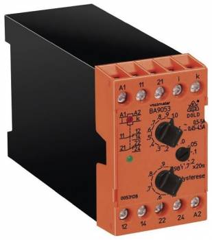
Dold 0053128 current relay BA9053/010 AC0,5-5A AC230V
| Lieske Part No. | 951056 |
|---|---|
| Mfg Part No | 0053128 |
| EAN-Code | 4030641531287 |
| Manufacturer | Dold |
| Here only | 263,30 EUR
313,33 EUR incl. VAT
|
Further information for Dold 0053128 current relay BA9053/010 AC0,5-5A AC230V
| Technical data | |
| 1- / 3-phase | 1 |
| Enclosure design | Switch cabinet |
| Output contacts | 2 C/O contacts |
| Width | 45 mm |
| Type | BA 9053 |
| Operate delay | |
| Variant | |
| Auxiliary voltage | AC 230 V |
| Contact equipping | 2 changeover contacts |
| Measuring range | AC 0,5 - 5 A |
| Start up delay | Without |
| Switching delay | 0 - 20 s |
| Approvals and Markings | UKCA, CCC |
| Variant | Overcurrent relay. Energized on trip. Time delay at response value |
Applications
The relay is designed for use in industrial and railway applications, where high operational safety and reliability are required. It monitors both DC and AC currents and is particularly suitable for detecting overloads in electrical systems, for example in motors, transformer installations, or process control. The galvanic isolation between auxiliary circuit and measuring circuit ensures safe and interference-free measurement, even under high disturbance voltages.
Functions and Equipment in Detail
The device features 2 changeover contacts as output contacts, which can be used to control external circuits. The measuring range covers AC 0.5 to 5 A, with the measured value being captured as the arithmetic mean of the rectified current. The devices are calibrated for sinusoidal AC currents in RMS value. The response delay is integrated and ensures that the relay does not react immediately to short-term current peaks, but only after the set delay time has elapsed. This prevents unwanted switching off during normal inrush currents.
Technology Explained Simply
Current measurement is performed via an internal measuring resistor (shunt), which is adapted according to the measuring range. For this model, the internal resistance is 3 mΩ. The auxiliary voltage is AC 230 V, connected via terminals A1 and A2. Operational readiness is indicated by a green LED, while a yellow LED signals the status of the output relay. The switching delay activates after exceeding the set value, enabling controlled response to overloads. The hysteresis, i.e., the difference between pickup and drop-out value, depends on the set value and ensures stable switching behavior without oscillations.
Compatibility and Accessories
The relay is designed for installation in enclosures and has a width of 45 mm, making it suitable for standard switchboards. It is compliant with IEC/EN 60255-1 and IEC/EN 60947-1 standards and carries the approvals UKCA and CCC. The galvanic isolation between measuring and auxiliary circuit enables safe integration into existing installations. It can also be used as an undercurrent relay, where the switching delay activates after falling below the hysteresis value.
Mounting and Installation
Mounting is done in standard switchboards using rail mounting. The connection terminals are clearly labeled: A1/A2 for auxiliary voltage, i/k for current input, and contacts 11-14 and 21-24 for the two changeover contacts. Adjustment of pickup and hysteresis values is done via rotary switches on the front. The devices are designed for maximum overload capacity, with the maximum permissible current for 3 seconds being 800 mA (for the 0.5–5 A measuring range). The measuring frequency can reach up to 5 kHz, enabling use in systems with high frequencies.
Advantages in Operation
Through precise and reliable current monitoring, the relay supports preventive maintenance and enables faster fault localization. The integrated switching delay prevents unnecessary switching off during short-term load peaks. The clear LED indication facilitates diagnosis during operation. The device is designed for industrial environments and offers high operational safety through galvanic isolation and robust construction. Compliance with standards IEC/EN 60255-1 and IEC/EN 60947-1 ensures safe and standard-compliant integration into existing systems.

This is an offer of:
79279 Vörstetten
https://industry-electronics.com
Tel. 07666/88499-0
Fax. 07666/88499-111
Diesen Artikel finden Sie unter:
industry-electronics.com/artikel/951056

Lieske Elektronik e.K.
Reutener Str. 1079279 Vörstetten
https://industry-electronics.com
Tel. 07666/88499-0
Fax. 07666/88499-111
Diesen Artikel finden Sie unter:
industry-electronics.com/artikel/951056