
Dold 0049438 overcurrent relay AC220-240V 0.5-5A
Industrial Material > Industrial relays and contactors > Switching units / measuring, control relay
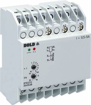
Dold 0049438 overcurrent relay AC220-240V 0.5-5A
| Lieske Part No. | 644844 |
|---|---|
| Mfg Part No | 0049438 |
| EAN-Code | 4030641494384 |
| Manufacturer | Dold |
| Here only | 408,55 EUR
486,17 EUR incl. VAT
|
Further information for Dold 0049438 overcurrent relay AC220-240V 0.5-5A
| Technical data | |
| 1- / 3-phase | 3 |
| Enclosure design | Distribution board |
| Output contacts | 2 C/O contacts |
| Width | 70 mm |
| Type | IP 9270 |
| Operate delay | |
| Variant | |
| Auxiliary voltage | AC 220 - 240 V |
| Contact equipping | 2 changeover contacts |
| Measuring range | 0,5 - 5 A |
| Time delay | 0,1 - 20 s |
| Variant | 3-phase current relay. Energized on trip |
Applications
This relay is intended for use in industrial and commercial electrical installations, particularly in systems with three-phase power supply, where precise current monitoring is required. Typical applications include monitoring motors, transformer installations, pumps, or other electrical loads, where an unexpected current increase may indicate a fault or overload. The adjustable switching delay allows short-term current surges, such as those occurring during motor start-ups, to be ignored, triggering a response only in the case of sustained overcurrents.
Functions and Features in Detail
The device features two changeover contacts as output contacts, which switch after an adjustable delay of 0.1 to 20 seconds when the set threshold value is exceeded. The threshold value is adjustable within the measuring range of 0.5 to 5 A, allowing flexible adaptation to different loads. The hysteresis is fixed at approximately 4 %, ensuring secure reset of the relay after the current has dropped. Operational readiness is indicated by a green LED, while exceeding the switching threshold triggers a red LED (I max). This visual feedback facilitates diagnosis during operation.
Technology Explained Simply
The relay operates on the operating current principle, meaning the output relay is activated in the event of a fault to trigger, for example, a contactor or fuse. Measurement is performed via a separate current measurement circuit, which is galvanically isolated from the auxiliary circuit to ensure safe and interference-free measurement. The time delay is designed to filter out short-term current surges that are not harmful, triggering a switching function only in the case of sustained overcurrents. The width is 70 mm, making it suitable for installation in standard installation distributors according to DIN 43880.
Compatibility and Accessories
The device is designed for use in three-phase networks and complies with the standard IEC/EN 60255-1. It is manufactured in I-form, intended for installation and industrial distributors, with a depth of 61 mm and connection terminals located at the bottom. Terminal markings follow the scheme A1/A2 for auxiliary voltage, i/k for the current measurement circuit, and Z1/Z2, Z3/Z4 for selecting the measuring range. The connection terminals are designed for mounting in distributors according to DIN 43880.
Mounting and Installation
Mounting is carried out in installation distributor enclosures according to DIN 43880. The width of 70 mm allows installation in standard distributors, with connection terminals located at the bottom. The auxiliary voltage is connected via terminals A1/A2, and the current measurement circuit via i/k. The measuring range selection is performed via bridges between terminals 11, 12, and 14. The connection terminals are designed for connection with cables that meet the respective requirements of the installation.
Operational Advantages
The relay provides precise and reliable current monitoring with adjustable parameters, allowing adaptation to different applications. The LED indicators enable quick visual control of the operational status. The galvanic isolation between the measurement and auxiliary circuits increases safety and prevents interference. The adjustable time delay reduces false tripping caused by short-term current surges. The design for installation distributors according to DIN 43880 ensures easy integration into existing systems.

This is an offer of:
79279 Vörstetten
https://industry-electronics.com
Tel. 07666/88499-0
Fax. 07666/88499-111
Diesen Artikel finden Sie unter:
industry-electronics.com/artikel/644844

Lieske Elektronik e.K.
Reutener Str. 1079279 Vörstetten
https://industry-electronics.com
Tel. 07666/88499-0
Fax. 07666/88499-111
Diesen Artikel finden Sie unter:
industry-electronics.com/artikel/644844