
Dold 0049136 level relay IL9151.122-450K-OHMDC24V0,2-20S
Industrial Material > Industrial relays and contactors > Switching units / measuring, control relay
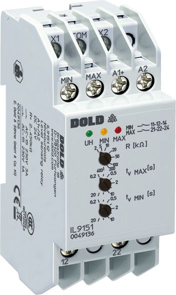
Dold 0049136 level relay IL9151.122-450K-OHMDC24V0,2-20S
| Lieske Part No. | 888089 |
|---|---|
| Mfg Part No | 0049136 |
| EAN-Code | 4030641491369 |
| Manufacturer | Dold |
| Here only | 201,24 EUR
239,48 EUR incl. VAT
|
Further information for Dold 0049136 level relay IL9151.122-450K-OHMDC24V0,2-20S
| Technical data | |
| Classification | Füllstandsüberwachung |
| Enclosure design | Distribution board |
| Measuring range max. | 450 kΩ |
| Output contacts | 2 x 1 C/O contacts |
| Width | 35 mm |
| Type | IL 9151 |
| Operate delay | |
| Variant | |
| Auxiliary voltage | DC 24 V |
| Contact equipping | 2 x 1 changeover contact |
| Response and release delay | 0,2 - 20 s |
| Response value | 2 - 450 kOhm |
| Approvals and Markings | UKCA, CCC |
| Variant | Time delay, when level rises over and drops under setting value |
Applications
This relay is suitable for level monitoring in containers with conductive media such as water, chemicals, or other liquids. It can also be used for limit temperature detection with PTC resistors. The application includes monitoring of minimum and maximum levels, with devices configurable for both 1-point and 2-point level control. The maximum cable length to the electrodes is 3000 m, enabling flexible installation even over long distances.
Functions and Equipment in Detail
The device features three electrode connections (MIN, MAX, COM) used for 2-point and 1-point level control. The pickup value is adjustable between 2 and 450 kΩ, allowing differentiation between liquid and foam. The pickup and release delay is separately adjustable for MIN and MAX levels, ranging from 0.2 to 20 seconds. Programming is done via a rotary switch, allowing selection between operating current and resting current principle. In the operating current principle, the output relay is activated in case of fault; in the resting current principle, it remains deactivated in case of fault.
Technology Explained Simply
The measurement circuit operates with an internally generated alternating voltage of approximately 30 Hz, preventing electrolytic effects in the liquid. Galvanic isolation of the measurement circuit from the mains ensures high immunity to interference. The auxiliary voltage is DC 24 V. The output contacts consist of two relays, each with a changeover contact (2 x 1 changeover). Operational readiness is indicated by a green LED, while the relay contact status is shown by yellow (MIN) and red (MAX) LEDs.
Compatibility and Accessories
The device is compatible with standard market-available electrodes. The reference electrode (COM) is typically mounted at the lowest point of the container. If the container is made of conductive material, it can serve as the reference electrode itself. The devices are specified according to IEC/EN 60255-1 and meet requirements for safe isolation as per IEC/EN 61140 and IEC/EN 60947-1. UKCA and CCC certifications are available.
Mounting and Installation
Mounting is done in installation and industrial distributors according to DIN 43880. The connection terminals are located at the bottom. Devices can be configured in various operating modes, with output relay actuation either jointly (2-point hysteresis) or separately (independent for MIN and MAX). The operating mode selection is made via a bridge between X1 and COM, and X2 and COM.
Advantages in Operation
The separate adjustability of pickup value and delay time for MIN and MAX levels allows precise adaptation to specific requirements. High immunity to interference and galvanic isolation of the measurement circuit ensure reliable measurement results. LED indicators provide clear visual feedback on the operational status. The device is designed for industrial environments and meets necessary standards for safety and reliability.

This is an offer of:
79279 Vörstetten
https://industry-electronics.com
Tel. 07666/88499-0
Fax. 07666/88499-111
Diesen Artikel finden Sie unter:
industry-electronics.com/artikel/888089

Lieske Elektronik e.K.
Reutener Str. 1079279 Vörstetten
https://industry-electronics.com
Tel. 07666/88499-0
Fax. 07666/88499-111
Diesen Artikel finden Sie unter:
industry-electronics.com/artikel/888089