
Dold 0047842 undervoltage relay 3AC230/400V
Industrial Material > Industrial relays and contactors > Switching units / measuring, control relay
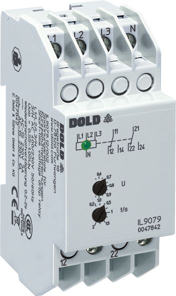
Dold 0047842 undervoltage relay 3AC230/400V
| Lieske Part No. | 547965 |
|---|---|
| Mfg Part No | 0047842 |
| EAN-Code | 4030641478421 |
| Manufacturer | Dold |
| Here only | 276,25 EUR
328,74 EUR incl. VAT
|
Further information for Dold 0047842 undervoltage relay 3AC230/400V
| Technical data | |
| 1- / 3-phase | 1, 3 |
| Auxiliary voltage | Without |
| Enclosure design | Distribution board |
| Nominal voltage max. | 3/N AC 400 / 230 V |
| Output contacts | 2 C/O contacts |
| Width | 35 mm |
| Type | IL 9079 |
| Variant | |
| Contact equipping | 2 changeover contacts |
| Nominal voltage | 3AC 230 / 400 V |
| Operate delay | 0,2 - 2 s |
| Reset value | 0,55 - 1,05 Un |
| Approvals and Markings | CCC |
| Variant | Für Netze mit Neutralleiter. Einstellbarer Rückfallwert |
Applications
This relay is suitable for monitoring 1- and 3-phase networks and can also be connected single-phase, in which case terminals L1, L2, and L3 must be bridged. It is specifically designed for networks with a neutral conductor and detects voltage interruptions lasting at least 20 ms at a drop value of 0.8 Un. Applications include installation and industrial distribution systems, particularly in industrial automation technology, where reliable network monitoring is essential for process safety.
Functions and Equipment in Detail
The device features 2 changeover contacts as output contacts, which are closed when the network is fault-free. The green LED indicator signals the normal operating condition. In the event of a fault, i.e., when at least one phase falls below the adjustable drop value (0.55 to 1.05 Un), the output relay drops out and the LED turns off. The re-energizing delay is adjustable between 0.2 and 2 seconds to generate a defined reset pulse. The device operates on the standby current principle, meaning the output relay is not activated in the event of a fault. Phase sequence is irrelevant, and the device operates independently of the phase arrangement in the network.
Technology Explained Simply
Voltage measurement is performed against the neutral conductor (N) for each phase. For devices without an N connection, L1 and L2 are measured against L3. The adjustable drop value allows flexible adaptation to different network conditions. The hysteresis is 4 %, ensuring stable switching behavior during voltage fluctuations. The response time for a phase failure is approximately 40 ms at a drop value of 0.8 Un. The rated frequency is 50/60 Hz, and the rated consumption is approximately 8 VA. The input resistances are approximately 150 kΩ.
Compatibility and Accessories
The relay is designed for use in installation distributors according to DIN 43880 and has a mounting width of 35 mm. It is available in the IL 9079 form factor, which features a depth of 59 mm and terminals located at the bottom. The devices are manufactured in accordance with IEC/EN 60255-1 and carry the CCC certification. The contact configuration consists of two changeover contacts with contact material made of AgNi. The thermal current rating is 4 A, and the measured rated voltage is AC 250 V.
Mounting and Installation
Mounting is carried out in standard installation distributors with a 35 mm mounting width. The terminals are located at the bottom, facilitating integration into existing control systems. The devices are designed for continuous overload capacity up to 1.1 Un. Terminal designations are clearly defined: L1, L2, L3, and N for voltage supply/measurement inputs, and 11, 12, 14, and 21, 22, 24 for the changeover contacts.
Operational Advantages
The adjustable re-energizing delay and rapid detection of short-term interruptions increase the reliability of control systems. The device enables preventive maintenance, as it detects and documents network disturbances early. Configuration as a fault memory (re-energizing lockout) is possible to prevent unwanted restarts. The green LED indicator provides visual feedback on the operating status, simplifying diagnosis in case of faults. The IL 9079 form factor is optimized for use in installation and industrial distributors, offering a compact, robust solution for industrial applications.

This is an offer of:
79279 Vörstetten
https://industry-electronics.com
Tel. 07666/88499-0
Fax. 07666/88499-111
Diesen Artikel finden Sie unter:
industry-electronics.com/artikel/547965

Lieske Elektronik e.K.
Reutener Str. 1079279 Vörstetten
https://industry-electronics.com
Tel. 07666/88499-0
Fax. 07666/88499-111
Diesen Artikel finden Sie unter:
industry-electronics.com/artikel/547965