
Dold 0045019 fuse monitor IL9075.01/001 400-440V
Industrial Material > Industrial relays and contactors > Switching units / measuring, control relay
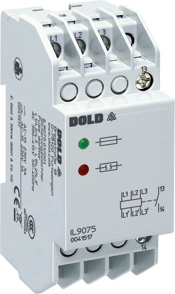
Dold 0045019 fuse monitor IL9075.01/001 400-440V
| Lieske Part No. | 1262559 |
|---|---|
| Mfg Part No | 0045019 |
| EAN-Code | 4030641450199 |
| Manufacturer | Dold |
| Here only | 128,73 EUR
153,19 EUR incl. VAT
|
Further information for Dold 0045019 fuse monitor IL9075.01/001 400-440V
| Technical data | |
| 1- / 3-phase | 3 |
| Enclosure design | Distribution board |
| Measuring range max. | 440 V |
| Output contacts | 1 NO contact, 2 C/O contacts |
| Standard measuring range | 3 AC 380 - 415 V |
| Width | 35 mm |
| Type | IL 9075 |
| Variant | |
| Contact equipping | 1 NO contact |
| Nominal voltage | AC 400 - 440 V 50 - 400 Hz |
| Approvals and Markings | CCC |
| Variant | De-energized on trip. Automatic reset |
Applications
The fuse monitor is designed for monitoring up to three load fuses in three-phase networks. It is typically used in installations where availability and operational safety are of high importance, such as in the automatic switching off and switching lockout of three-phase motors. The application is in networks with a voltage up to 3 AC 690 V, with the device designed for the standard measurement range of 3 AC 380–415 V. The rated voltage is AC 400–440 V at a frequency of 50–400 Hz.
Functions and equipment in detail
The device operates on the residual current principle, in which the output relay is not activated in the event of a fault. It features a closing contact (1 NO) as the output contact. Monitoring is independent of the network rotation direction and is reliable even in asymmetric or harmonic-loaded networks, as well as with regenerative motors. The response time is shorter than that of motor protection switches. Indication is provided by two LEDs: a green LED indicates intact fuses, while a red LED indicates a fuse failure.
Technology explained simply
The fuse monitor monitors the voltage before and after the load fuses. In the event of a fuse failure, the voltage after the fuse is no longer transmitted, which is detected by the device. The internal resistance of the measurement paths is in the MOhm range (over 2000 Ohm/V), thus meeting the requirements for touch voltage. Programming of the operating current or residual current principle is done via terminals X3–X5. The cable length for this programming input must not exceed 3 m.
Compatibility and accessories
The device is suitable for all common fuse types and sizes. It is designed in the I form factor, with a mounting width of 35 mm and a mounting depth of 59 mm. The connection terminals are located at the bottom and are intended for installation and industrial distributors according to DIN 43880. The CCC certification is available.
Mounting and installation
Mounting is done in installation or industrial distributors. The terminals are located at the bottom, which facilitates integration into standard distributor constructions. De-energizing requires switching off the upstream main switch.
Advantages in operation
Early detection of fuse failures enables preventive maintenance and prevents costly damage. The operational safety and availability of the installation are increased. The reliability of monitoring even under difficult network conditions provides a stable foundation for operation. The device is rotation-direction independent and suitable for a wide range of application scenarios in industrial electrotechnics.

This is an offer of:
79279 Vörstetten
https://industry-electronics.com
Tel. 07666/88499-0
Fax. 07666/88499-111
Diesen Artikel finden Sie unter:
industry-electronics.com/artikel/1262559

Lieske Elektronik e.K.
Reutener Str. 1079279 Vörstetten
https://industry-electronics.com
Tel. 07666/88499-0
Fax. 07666/88499-111
Diesen Artikel finden Sie unter:
industry-electronics.com/artikel/1262559