
Dold 0040804 insulation monitor AI 897 AC45-400Hz 400V
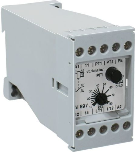
Dold 0040804 insulation monitor AI 897 AC45-400Hz 400V
| Lieske Part No. | 1001657 |
|---|---|
| Mfg Part No | 0040804 |
| EAN-Code | 4030641408046 |
| Manufacturer | Dold |
| Here only | 268,13 EUR
319,07 EUR incl. VAT
|
Further information for Dold 0040804 insulation monitor AI 897 AC45-400Hz 400V
| Technical data | |
| Auxiliary voltage | Without |
| Enclosure design | Switch cabinet |
| IMD type | AC |
| Nominal voltage IT system | AC 24 - 500 V |
| Response value | 10 - 80 kΩ |
| Response value type | Adjustable |
| Width | 45 mm |
| Type | AI 897 |
| Variant | |
| Alarm value | 10 - 80 kOhm |
| Contact equipping | 1 changeover contact |
| Nominal voltage | AC 400 V 45 - 400 Hz |
| Variant | Settable response value |
Applications
The insulation monitor is intended for use in industrial and technical installations where safety is ensured by detecting insulation faults in the network. It is suitable for IT systems with nominal voltages from AC 24 to 500 V and frequencies between 45 and 400 Hz. Monitoring is performed via a measuring circuit connected to one phase; in three-phase systems, this is sufficient, as the phases are connected via the supplying transformer with low resistance (approximately 3–5 Ω), allowing faults on unconnected phases to be detected. Only one insulation monitor may be installed in a network to avoid false alarms.
Functions and Equipment in Detail
The device features an adjustable trigger value between 10 and 80 kΩ, which can be set continuously using a screwdriver. The trigger value is simulated via an internal test resistor corresponding to an earth resistance below 10 kΩ. The measuring voltage is DC 18 V, and the maximum measuring current at an earth resistance of 0 Ω is less than 0.1 mA. The response delay is less than 4.2 seconds when the earth resistance drops from infinite to 90 % of the trigger value at a trigger value of 50 kΩ and a capacitance of 1 μF. When dropping to 0 Ω, the delay is approximately 2 seconds.
Technology Explained Simply
The insulation monitor operates on the idle current principle, where the output relay is not activated in the event of a fault, but is only triggered via a changeover contact when an insulation fault occurs. The function is programmable: bridging terminals LT1 and LT2 activates memory behavior, where the alarm can only be reset via an external reset button. Without bridging, hysteresis behavior is active, where the alarm automatically resets when the insulation resistance rises above the trigger value again. The hysteresis is approximately 50 % at a trigger value of 50 kΩ. The trigger uncertainty is ±15 %.
Compatibility and Accessories
The device includes an integrated test button PT to check the device’s functionality. External test buttons can be connected to terminals PT1 and PT2. Similarly, external reset buttons can be connected to LT1 and LT2 to utilize memory behavior. The contact configuration consists of a changeover contact rated for a maximum switching voltage of AC 400 V. The thermal current is 6 A, and the switching capacity complies with standards IEC/EN 60947-5-1 (AC 15 and DC 13). The electrical life is at least 300,000 switching operations at 10 A and AC 250 V, and the mechanical life is at least 30 million switching operations.
Mounting and Installation
Mounting is performed in enclosures with a width of 45 mm. The operating temperature range is from -20 °C to +60 °C, and the storage temperature range is from -25 °C to +70 °C. The operating altitude is limited to below 2000 m. The housing protection rating is IP 40, protecting against contact with moving parts and solid objects. Creepage and clearance distances correspond to pollution degree 2 and a rated impulse voltage of 4 kV. The insulation test voltage is AC 2.5 kV for 1 second.
Operational Advantages
The insulation monitor provides reliable, low-maintenance monitoring without auxiliary voltage. The adjustable trigger threshold allows adaptation to the specific requirements of the network. The programmable functions for memory behavior and hysteresis enable flexible adaptation to operation. Integrated test and reset buttons, as well as the possibility to connect external buttons, enhance usability. EMC tests according to IEC/EN 61000-4-2 to -4-6 ensure robust operation in electromagnetically demanding environments. Radio frequency interference suppression complies with emission limit class B according to EN 55011.
Protection Rating and Environmental Conditions
The device is designed for indoor use, as the IP 40 protection rating does not provide weather protection. The operating temperature range is limited to -20 °C to +60 °C, with guaranteed functionality within the permissible voltage range. Storage is permitted up to +70 °C. The operating altitude is limited to below 2000 m above sea level.
Contacts and Switching Capacity
The contact configuration consists of a changeover contact. The maximum switching voltage is AC 400 V. The thermal current Ith is 6 A. The switching capacity complies with standards IEC/EN 60947-5-1: for AC 15, the switching capacity is 10 A / AC 230 V for the closing contact and 5 A / AC 230 V for the opening contact. For DC 13, it is 1 A / DC 24 V. The electrical life is at least 300,000 switching operations at 10 A and AC 250 V. The mechanical life is at least 30 million switching operations. The short-circuit withstand requires a maximum fuse rating of 5 A gG / gL.
EMC and Safety
The device meets the requirements of the EMC directive. Electrostatic discharge is 8 kV (air discharge) according to IEC/EN 61000-4-2. Radio frequency field strength is 10 V/m in the range 80 MHz to 2.7 GHz according to IEC/EN 61000-4-3. Fast transients are 2 kV according to IEC/EN 61000-4-4. Surge voltages between supply lines are 2 kV, and between lines and earth are 4 kV according to IEC/EN 61000-4-5. Conducted RF interference is 10 V according to IEC/EN 61000-4-6. Radio frequency interference suppression complies with emission limit class B according to EN 55011. The housing protection rating is IP 40 according to IEC/EN 60529.
Connection Terminals and Functions
Terminals A1 and A2 are for connecting the AC auxiliary voltage and the measuring circuit. PE is the connection for the protective conductor. PT1 and PT2 are for connecting an external test button. LT1 and LT2 are for connecting an external reset button or for programming memory or hysteresis behavior. Terminals 11, 12, and 14 are the connections for the alarm indicator relay (1 changeover contact). The functions are programmable: bridging LT1 and LT2 activates memory behavior, while no bridging activates hysteresis behavior.
Approvals and Markings
The device complies with standards IEC/EN 61557-8 and IEC/EN 60947-5-1. Approvals and markings are listed in the datasheet. The operating temperature range is limited to -20 °C to +60 °C, and the storage temperature range is -25 °C to +70 °C. The operating altitude is limited to below 2000 m. Creepage and clearance distances correspond to pollution degree 2 and a rated impulse voltage of 4 kV. The insulation test voltage is AC 2.5 kV for 1 second.
General Data
The nominal operating mode is continuous operation. The operating temperature range is from -20 °C to +60 °C, and the storage temperature range is from -25 °C to +70 °C. The operating altitude is limited to below 2000 m. Creepage and clearance distances correspond to pollution degree 2 and a rated impulse voltage of 4 kV. The insulation test voltage is AC 2.5 kV for 1 second. The housing protection rating is IP 40. EMC tests according to IEC/EN 61000-4-2 to -4-6 are fulfilled. Radio frequency interference suppression complies with emission limit class B according to EN 55011.
Functional Safety and Reliability
The insulation monitor AI 897 offers high reliability through the idle current principle and programmable functions. The adjustable trigger threshold and hysteresis ensure precise and disturbance-free alarm signaling. Integrated test and reset buttons, as well as the possibility to connect external buttons, enhance usability. EMC tests ensure robust operation in electromagnetically demanding environments. The mechanical life of at least 30 million switching operations and the electrical life of at least 300,000 switching operations at 10 A and AC 250 V guarantee a long service life.

This is an offer of:
79279 Vörstetten
https://industry-electronics.com
Tel. 07666/88499-0
Fax. 07666/88499-111
Diesen Artikel finden Sie unter:
industry-electronics.com/artikel/1001657

Lieske Elektronik e.K.
Reutener Str. 1079279 Vörstetten
https://industry-electronics.com
Tel. 07666/88499-0
Fax. 07666/88499-111
Diesen Artikel finden Sie unter:
industry-electronics.com/artikel/1001657