
Dold 0039962 speed monitor BA9055/110 AC230V
Industrial Material > Industrial relays and contactors > Switching units / measuring, control relay
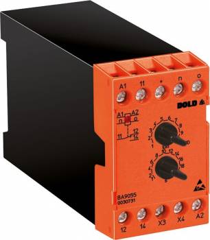
Dold 0039962 speed monitor BA9055/110 AC230V
| Lieske Part No. | 1313025 |
|---|---|
| Mfg Part No | 0039962 |
| EAN-Code | 4030641399627 |
| Manufacturer | Dold |
| Here only | 278,85 EUR
331,83 EUR incl. VAT
|
Further information for Dold 0039962 speed monitor BA9055/110 AC230V
| Technical data | |
| Classification | Drehzahlüberwachung |
| Enclosure design | Switch cabinet |
| Measuring range max. | 10000 IPM |
| Output contacts | 1 C/O contact |
| Width | 45 mm |
| Type | BA 9055 |
| Operate delay | |
| Variant | |
| Auxiliary voltage | AC 230 V |
| Contact equipping | 1 changeover contact |
| Setting range | 10 - 100 IPM |
| Start up delay | Without |
| Approvals and Markings | UKCA |
| Variant | Without start up delay time. Standstill and underspeed monitoring in open circuit operation. Overspeed monitoring in closed circuit operation |
Applications
The speed monitor is used in systems where maintaining a specific speed is critical for functionality or safety. Typical applications include conveyor belts, conveyor systems, or production plants where multiple drives must operate at coordinated speeds. Monitoring prevents damage to machines or products that could result from unintended standstills, excessively low, or excessively high speeds. The device is designed for industrial environments where reliable and low-maintenance monitoring is required.
Functions and Equipment in Detail
The device detects standstill, under-speed, and over-speed conditions. The adjustable range is between 10 and 100 pulses per minute (IPM), with a maximum measurement range up to 10,000 IPM. The response delay is activated, meaning the device incorporates a short delay when responding to filter out brief disturbances. Over-speed monitoring operates on the no-load current principle, while standstill and under-speed monitoring operate on the load current principle. The hysteresis is 2% of the set response value, ensuring stable switching behavior. The start-up bypass is not available in this variant, so the device becomes active immediately after power supply is applied. The power supply for the proximity switch is integrated within the device and provides DC 24 V with a maximum current of 40 mA. The input is designed for pnp sensors.
Technology Explained Simply
The technology of the speed monitor is based on the principle of frequency comparison. A proximity switch generates pulses proportional to the speed. These pulses are compared within the device with an internal, adjustable reference frequency. In under-speed monitoring, the output relay is energized when the measured frequency falls below the reference frequency. In over-speed monitoring, the relay is energized when the measured frequency exceeds the reference frequency. The switching delay is very short, as the device does not operate in an integrated mode. The response time can be calculated using the formula tv = 60 / (n × z), where n is the speed in rpm and z is the number of teeth or cams on the measuring wheel. LEDs indicate the status of the auxiliary voltage and output contacts.
Compatibility and Accessories
The speed monitor is compatible with proximity switches featuring a pnp output. The integrated power supply for the sensor (DC 24 V, max. 40 mA) allows direct connection without requiring an additional power source. The device is specified according to IEC/EN 60255-1 and carries the UKCA mark. It is designed for use in enclosures and fits standard 35-mm rails. Terminal markings include power supply (A1, A2), input (n), programming terminals (X3, X4), and output contacts (11, 12, 14). The terminals are designed for secure and reliable connections.
Mounting and Installation
Mounting is done in an enclosure on a 35-mm rail. The width of 45 mm allows for compact placement. The terminals are clearly labeled: A1 and A2 for auxiliary voltage (AC 230 V), n for the input from the proximity switch, X3 and X4 as programming terminals, and 11, 12, 14 for the output contacts (changeover). The power supply for the proximity switch is integrated, so no additional supply is required. The response value is adjusted using a rotary knob on the device. The start-up bypass is not available in this variant, so no bridge connection between terminals X3 and X4 is required.
Advantages in Operation
The speed monitor provides reliable and simple speed monitoring in industrial systems. The adjustable response frequency allows application-specific adaptation. The integrated power supply for the proximity switch reduces the number of required external components. Clear indication via LEDs simplifies diagnostics during operation. The device is designed for use in enclosures and complies with IEC/EN 60255-1 and the UKCA mark. The compact design (45 mm width) allows flexible installation in existing control systems. Monitoring of standstill, under-speed, and over-speed protects machines and products from damage caused by unwanted operating conditions.

This is an offer of:
79279 Vörstetten
https://industry-electronics.com
Tel. 07666/88499-0
Fax. 07666/88499-111
Diesen Artikel finden Sie unter:
industry-electronics.com/artikel/1313025

Lieske Elektronik e.K.
Reutener Str. 1079279 Vörstetten
https://industry-electronics.com
Tel. 07666/88499-0
Fax. 07666/88499-111
Diesen Artikel finden Sie unter:
industry-electronics.com/artikel/1313025