
Dold 0033897 IK8701.12 DC24V relay
Industrial Material > Industrial relays and contactors > Switching units / measuring, control relay
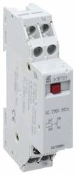
Dold 0033897 IK8701.12 DC24V relay
| Lieske Part No. | 906670 |
|---|---|
| Mfg Part No | 0033897 |
| EAN-Code | 4030641338978 |
| Manufacturer | Dold |
| Here only | 59,04 EUR
70,26 EUR incl. VAT
|
Further information for Dold 0033897 IK8701.12 DC24V relay
| Technical data | |
| Enclosure design | Distribution board |
| Output contacts max. | 2 C/O contacts |
| Thermal current Ith max. | 16 A |
| Width | 17,5 mm |
| Type | IK 8701 |
| Initiator triggering | |
| Suppressor circuit on the coil input | |
| Variant | |
| Contact equipping | 2 changeover contacts |
| Nominal voltage | DC 24 V |
Applications
This relay is designed for use in industrial control systems, particularly in installations where lamp loads need to be switched. It can be used as an input coupling relay to forward signals from sensors or other devices to a PLC, or as an output coupling relay to switch PLC-controlled loads. The contact configuration with 2 changeover contacts allows for flexible switching configurations, for example, for controlling motors, heaters, or lighting units. Use in systems operating with direct current, especially at DC 24 V, is typical for industrial automation systems.
Functions and equipment in detail
The device features a manual operation button on the front, which serves both for manual activation of the contacts and for visual indication of the switching position. When the relay is energized, the button is pushed in; when de-energized, it is flush with the front edge of the housing. This function allows for easy checking of the operating status without additional measuring instruments. The contacts are actuated via a toggle armature with a plunger; when the excitation voltage drops, the armature is returned to its resting position by a spring. The maximum thermal current rating (Ith) is 16 A, ensuring high load capacity under continuous operation.
Technology explained simply
The relay coil is connected to DC 24 V via terminals A1+ and A2+. The protective circuit at the coil input protects the device against reverse polarity and acts as a freewheeling diode to suppress switching surges when switching inductive loads. The contacts are designed for switching operations and can handle loads up to 16 A thermally. The standard contact gap is 3 mm, ensuring reliable switching performance even under high switching cycles. The contact configuration with 2 changeover contacts allows for parallel control of multiple loads or the implementation of switching circuits with feedback.
Compatibility and accessories
The relay is designed for use in standard installation distributor boxes and fits into widths of 17.5 mm. It is compatible with 2-wire initiators, with an allowable residual current of ≤ 3 mA. Control is achieved via terminals A1+ and A2+, where polarity is fixed for DC devices. The use of parallel compensation, for example for HQ lamps, is possible, with a maximum compensation capacitance of 100 μF. The contact configuration may include up to 4 changeover contacts depending on the variant, with the variant described here featuring 2 changeover contacts.
Mounting and installation
The device is installed into an installation distributor, with the width of 17.5 mm enabling mounting in standard distributor boxes. The terminals are clearly labeled (A1+, A2+ for the coil, 11, 12, 14, etc. for contacts), allowing for unambiguous assignment. Mounting is done by snapping into the corresponding rail of the distributor. The manual operation button allows for easy testing of the switching function before and after commissioning.
Advantages in operation
The relay offers high reliability for industrial switching operations, supported by the protective circuit at the coil input and the high thermal current rating. The integrated switching position indicator and the manual operation button facilitate maintenance and troubleshooting. Compatibility with 2-wire initiators and the possibility of parallel compensation extend the range of applications. The construction in accordance with EN 60947-5-1 ensures compliance with the required safety and functional requirements for control technology.

This is an offer of:
79279 Vörstetten
https://industry-electronics.com
Tel. 07666/88499-0
Fax. 07666/88499-111
Diesen Artikel finden Sie unter:
industry-electronics.com/artikel/906670

Lieske Elektronik e.K.
Reutener Str. 1079279 Vörstetten
https://industry-electronics.com
Tel. 07666/88499-0
Fax. 07666/88499-111
Diesen Artikel finden Sie unter:
industry-electronics.com/artikel/906670