
Dold 0032082 thermistor motor protection relay MK9052.11/100 230V
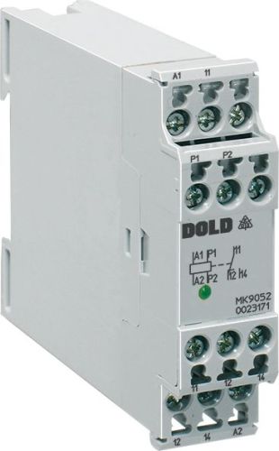
Dold 0032082 thermistor motor protection relay MK9052.11/100 230V
| Lieske Part No. | 1153683 |
|---|---|
| Mfg Part No | 0032082 |
| EAN-Code | 4030641320829 |
| Manufacturer | Dold |
| Here only | 205,58 EUR
244,64 EUR incl. VAT
|
Further information for Dold 0032082 thermistor motor protection relay MK9052.11/100 230V
| Technical data | |
| Classification | Thermistor-Motorschutz |
| Enclosure design | Switch cabinet |
| Measuring range max. | > 3 kΩ |
| Output contacts | 2 C/O contacts |
| Width | 22,5 mm |
| Type | MK 9052 |
| Variant | |
| Auxiliary voltage | AC 230 V |
| Contact equipping | 1 changeover contact |
| Variant | With electro magnetic reclosing interlock (manual reset function) |
Applications
This motor protection relay is intended for use in industrial plants where motors may be thermally overloaded due to high switching frequency, heavy start-up, single-phase operation, impaired cooling, or high ambient temperature. It protects motors from damage caused by overheating and extends the service life of drive technology. The application typically involves use in combination with PTC thermistors integrated into the motor, whose resistance increases with rising temperature. Up to 6 thermistors can be connected in series to ensure reliable monitoring.
Functions and Features in Detail
The device includes a wire break detection feature in the sensor circuit, ensuring that a defective or broken sensor is detected and the relay responds accordingly. The pickup value is ≥ 3 kΩ, and the drop-out value is ≤ 1.8 kΩ. The measurement circuit load is approximately 1 mW at a resistance of 1.5 kΩ, and the measurement voltage is approximately 1.2 V. The output contacts are rated for a switching capacity of 3 A / AC 230 V (make) and 1 A / AC 230 V (break). The electrical life is over 800,000 switching cycles at 3 A and AC 230 V, while the mechanical life exceeds 20 million switching cycles. The maximum short-circuit withstand requires a fuse of 4 A gG / gL.
Technology Explained Simply
The relay operates on the rest current principle, meaning the output relay is activated during normal operation and drops out when the pickup value is reached. This ensures a safe shutdown, as the contact is not activated in the event of a fault. The reset lockout (reset function) prevents automatic re-energizing after a fault; manual reset is required. The LED on the device indicates the switching state, allowing the operating condition to be visually checked. The operating temperature range is from -20 °C to +60 °C, and the device is designed for operation at altitudes below 2000 m.
Compatibility and Accessories
The relay is compatible with thermistors (PTC resistors) specifically developed for motor protection. Up to 6 sensors can be used in series. The terminal connections are designed for conductor cross-sections of 2 x 2.5 mm² (solid) or 2 x 1.5 mm² (stranded wire with ferrule DIN 46228-1/-2/-3/-4). The terminals are secured using flat terminals with self-lifting connection washers. The terminal markings comply with standard EN 50005.
Mounting and Installation
Mounting is done on a DIN rail (DIN 46228-1/-2/-3/-4) inside the enclosure. The tightening torque for the terminals is 0.4 Nm. The device dimensions are 22.5 mm (width) x 82 mm (height) x 99 mm (depth). The enclosure protection rating is IP 40, and the terminals are rated IP 20. The device is designed for continuous operation and complies with standard IEC/EN 60947-8. EMC requirements are met according to IEC/EN 61000-4-2 to -4-6, including radio interference suppression according to Class B limit (EN 55011). The vibration resistance is 0.35 mm amplitude at a frequency of 10 to 55 Hz.
Operational Advantages
The motor protection relay provides reliable monitoring of motor heat and protects against thermal damage. The integrated wire break detection enhances safety by detecting a faulty sensor. The reset lockout prevents unintended restarts, which is important in safety-critical systems. The compact design and DIN rail mounting facilitate installation in existing enclosures. The long service life and high switching endurance ensure low-maintenance operation over an extended period.
Protection Rating and Environmental Conditions
The enclosure is made of thermoplastic with V0 flammability rating according to UL Subject 94, ensuring good flame resistance. The operating temperature range is from -20 °C to +60 °C, and the storage temperature range is also from -20 °C to +60 °C. The operating altitude is limited to below 2000 m. The creepage and clearance distances correspond to a rated impulse voltage of 4 kV at pollution degree 2 (IEC 60664-1). The climatic resistance is certified according to IEC/EN 60068-1 (20 / 060 / 04).
Connection and Signal Description
The terminal connections are marked as follows: A1/A2 for supply voltage, P1/P2 for thermistor input, and contacts 11, 12, 14 as well as 21, 22, 24 for the changeover contacts. The LED indicates the state of the output relay. The auxiliary voltage is AC 230 V, the nominal frequency is 50/60 Hz, and the nominal power consumption is 1.8 VA. The thermal current rating (Ith) is 5 A.
Approvals and Standards
The device complies with standard IEC/EN 60947-8 and is zero-voltage safe according to VDE 0113, § 5.4.2. EMC requirements are met according to IEC/EN 61000-4-2 to -4-6. Radio interference suppression complies with Class B limit according to EN 55011. The enclosure protection rating is IP 40, and the terminals are rated IP 20. Terminal markings follow EN 50005.

This is an offer of:
79279 Vörstetten
https://industry-electronics.com
Tel. 07666/88499-0
Fax. 07666/88499-111
Diesen Artikel finden Sie unter:
industry-electronics.com/artikel/1153683

Lieske Elektronik e.K.
Reutener Str. 1079279 Vörstetten
https://industry-electronics.com
Tel. 07666/88499-0
Fax. 07666/88499-111
Diesen Artikel finden Sie unter:
industry-electronics.com/artikel/1153683