Eltako 30400865 - FSR71NP 4x 230V Wireless Actuator 4 channel impulse switching relay 30
Installation > Home Automation > Bus systems - radio
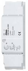
Eltako 30400865 - FSR71NP 4x 230V Wireless Actuator 4 channel impulse switching relay 30
| Lieske Part No. | 332466 |
|---|---|
| Mfg Part No | 30400865 |
| EAN-Code | 4010312316269 |
| Manufacturer | Eltako |
| Here only | 108,43 EUR
129,03 EUR incl. VAT
|
Further information for Eltako 30400865 - FSR71NP 4x 230V Wireless Actuator 4 channel impulse switching relay 30
Impulse switching relay with 4 channels, 1 normally open contact each, not potential-free 4A/250V AC. With light scene control via PC or with radio buttons. Encrypted radio, bidirectional radio and repeater function can be switched on. Standby loss only 0.8 watts. Installation in the 230V mains connection cable, for example in false ceilings and lights. 166mm long, 46mm wide and 31mm deep. With cable strain relief. If the supply voltage fails, the device is switched off in a defined manner. The channels can be taught in independently of one another as ES or ER channels. Scene control: With one of the four control signals from a button with double rocker that has been taught in as a scene button, several channels of one or more FSR71NP-4x can be switched on or off for one scene each. Central commands on the PC are sent using the GFVS building radio visualization and control software. To do this, teach one or more FSR71NP-4x on the PC. The buttons are taught in using the rotary switches and the 4 channels are tested if necessary. For normal operation, the middle and lower rotary switches are then set to AUTO. The upper rotary switch can be used to set the EW time (0-120 seconds) for relays or the RV time (0-120 minutes) for impulse switches for all channels. If wireless motion brightness sensors FBH (master) and/or FBH (slave) are taught in, the upper rotary switch is used to set the switching threshold at which the lighting switches on or off separately for each channel. Settings for the upper rotary switch as per the operating instructions. If FAH60 wireless brightness sensors are taught in, the switching threshold at which the lighting switches on or off depending on the brightness is set separately for each channel using the upper rotary switch (from approx. 0 lux in position 0 to approx. 50 lux in position 120). A hysteresis of approx. 300 lux between switching on and off is fixed. An additional RV time is ignored. Only one FBH or FAH can be taught in per channel. However, one FBH or FAH can be taught in several channels. If FTK wireless window-door contacts or Hoppe window handles are taught in, different functions can be set using the middle rotary switch in the AUTO 1 to AUTO 4 positions and a maximum of 116 FTKs can be linked: AUTO 1 = window closed, then output active. AUTO 2 = window open, then output active. In the AUTO 3 and AUTO 4 positions, the FTKs programmed on a channel are automatically linked. With AUTO 3, all FTKs must be closed for the working contact to close (e.g. for climate control). With AUTO 4, one open FTK is sufficient to close the working contact (e.g. for alarm notification or switching on the power supply of an extractor hood). One or more FTKs can be programmed into several channels so that different functions are possible simultaneously for each FTK.After a power failure, the link is re-established by a new signal from the FTK or with the next status message after 15 minutes. An additionally set RV time is ignored. If water sensors are taught-in, different functions can be set using the middle rotary switch in the positions AUTO 1 to AUTO 4. AUTO 1 = no water, then working contact closed. AUTO 2 = water, then working contact closed. In the positions AUTO 3 and AUTO 4, the water sensors taught-in on a channel are automatically linked. With AUTO 3, all water sensors must have reported no water for the working contact to close. The working contact opens when a water sensor reports water. With AUTO 4, the working contact closes when a water sensor reports water; the working contact only opens when all water sensors have reported no water. An additionally set RV time is ignored. The LED under the upper rotary switch accompanies the teaching process in accordance with

This is an offer of:
79279 Vörstetten
https://industry-electronics.com
Tel. 07666/88499-0
Fax. 07666/88499-111
Diesen Artikel finden Sie unter:
industry-electronics.com/artikel/332466

Lieske Elektronik e.K.
Reutener Str. 1079279 Vörstetten
https://industry-electronics.com
Tel. 07666/88499-0
Fax. 07666/88499-111
Diesen Artikel finden Sie unter:
industry-electronics.com/artikel/332466