Eltako FAE14SSR - RS485 bus actuator 2 zones solid state relays
Installation > Home Automation > Bus systems - radio
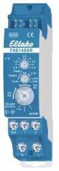
Eltako FAE14SSR - RS485 bus actuator 2 zones solid state relays
| Lieske Part No. | 841334 |
|---|---|
| Mfg Part No | 30014029 |
| EAN-Code | 4010312314173 |
| Manufacturer | Eltako |
| Here only | 71,25 EUR
84,79 EUR incl. VAT
|
Further information for Eltako FAE14SSR - RS485 bus actuator 2 zones solid state relays
Silent individual room control with 2 channels, 400W. 2 solid-state relays, not potential-free. Bidirectional. Standby loss only 0.1 watts. Modular device for mounting on a mounting rail. Connection to the Eltako RS485 bus. Cross-wiring of bus and power supply with jumper. If both relays are switched on, 0.4 watts are required. The nominal switching capacity of 400W applies to one contact and also to the sum of both contacts. When the load = setpoint temperature, it is switched off. When the actual temperature = setpoint temperature, it is switched off. When the actual temperature <= (setpoint temperature - hysteresis), it is switched on. In cooling mode, the signs are reversed. The type of actuator connected is selected using the lower rotary switch: SA NC for actuator NC (normally closed) or SA NO for actuator NO (normally open). If radio window-door contacts FTK or Hoppe window handles are taught in, they are linked using an OR function. If one or more windows are open, the output remains switched off. However, frost protection remains active in heating mode. If motion detectors underfloor heating are taught in, they are linked using an AND function. If all underfloor heating systems have not reported movement, the system switches to standby reduction mode: In heating mode, the target temperature is reduced by 2°, and in cooling mode it is raised by 2°. As soon as an underfloor heating system reports movement again, it switches to normal mode. If an underfloor heating system and radio button are taught in, the last telegram received always applies. If movement is detected, an underfloor heating system switches a reduction mode selected with the radio button off again. If a radio button is taught in, the 4 buttons are permanently assigned the following functions: Top right: Normal mode (can also be activated using the timer with the on function). Bottom right: Night-time reduction by 4°, in cooling mode increase by 4° (can also be activated by timer with the off function). Top left: Stand-by reduction by 2°, in cooling mode increase by 2°. Bottom left: Off (frost protection active in heating mode, permanently off in cooling mode). Fault mode: If no radio telegram is received from a temperature sensor for more than 1 hour, the LED lights up and the system switches to fault mode: In heating mode, PWM 1 switches on for 1.2 minutes and switches off for 2.8 minutes. For PWM 2 and 2-Pt, the times are 4.5 minutes on and 10.5 minutes off. In cooling mode, it switches off. If a radio telegram is received again, the LED goes out and the system automatically switches back to normal mode. The LED under

This is an offer of:
79279 Vörstetten
https://industry-electronics.com
Tel. 07666/88499-0
Fax. 07666/88499-111
Diesen Artikel finden Sie unter:
industry-electronics.com/artikel/841334

Lieske Elektronik e.K.
Reutener Str. 1079279 Vörstetten
https://industry-electronics.com
Tel. 07666/88499-0
Fax. 07666/88499-111
Diesen Artikel finden Sie unter:
industry-electronics.com/artikel/841334