Eltako FSR14-2x - RS485 bus switching actuator impulse switch relay
Installation > Home Automation > EIB material
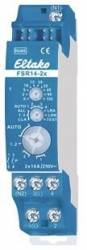
Eltako FSR14-2x - RS485 bus switching actuator impulse switch relay
| Lieske Part No. | 826565 |
|---|---|
| Mfg Part No | 30014002 |
| EAN-Code | 4010312313718 |
| Manufacturer | Eltako |
| Here only | 68,63 EUR
81,67 EUR incl. VAT
|
Further information for Eltako FSR14-2x - RS485 bus switching actuator impulse switch relay
Impulse switching relay with 2 channels, 1+1 normally open contact potential-free 16A/250V AC, 230V LED lamps up to 400W, incandescent lamps 2000W, with DX technology. Bidirectional. Standby loss only 0.1 watts. Modular device for mounting on DIN-EN 60715 TH35 mounting rail. 1 division unit = 18mm wide, 58mm deep. Connection to the Eltako RS485 bus. Cross-wiring of bus and power supply with jumper. With the patented Eltako duplex technology, the normally potential-free contacts can still switch at zero crossing when switching 230V AC 50Hz, thus drastically reducing wear. To do this, simply connect the N conductor to terminal (N1) and L to 1(L) and/or N to (N2) and L to 3(L). This results in an additional standby loss of just 0.1 watts. If the supply voltage fails, the switching state is retained. When the supply voltage returns, it is switched off in a defined manner. The channels can be taught in independently of one another as ES and/or ER channels. Scene control: Using one of the four control signals from a button with a double rocker that has been taught in as a scene button, several channels of one or more FSR14-2x can be switched on or off for one scene each. Central commands can be sent using radio buttons and/or a Professional Smart Home Controller. The buttons are taught in using the rotary switches and the 2 channels are tested if necessary. For normal operation, the middle and lower rotary switches are then set to AUTO. With the upper rotary switch, the EW time (0-120 seconds) for relays or the RV time (0-120 minutes) for impulse switches can be set the same for all channels if necessary. If wireless motion brightness sensors FBH (master) and/or FBH (slave) are taught-in, the switching threshold at which the lighting switches on or off is set separately for each channel using the upper rotary switch. Settings for the upper rotary switch are as per the operating instructions. If wireless brightness sensors are taught-in, the switching threshold at which the lighting switches on or off depending on the brightness is set separately for each channel using the upper rotary switch (from approx. 0 lux in position 0 to approx. 50 lux in position 120). A hysteresis of approx. 300 lux between switching on and off is fixed. An additionally set RV time is ignored. Only one FBH (master) or FAH can be taught-in per channel. However, one FBH (master) or FAH can be taught into multiple channels. If wireless window-door contacts FTK or window handle sensors FFG7B are taught in, different functions can be set using the middle rotary switch in the positions AUTO 1 to AUTO 4 and a maximum of 116 FTKs can be linked: AUTO 1 = window closed, then output active. AUTO 2 = window open, then output active. In the positions AUTO 3 and AUTO 4, the FTKs taught in on a channel are automatically linked.With AUTO 3, all FTKs must be closed for the working contact to close (e.g. for climate control). With AUTO 4, one open FTK is sufficient to close the working contact (e.g. for alarm notification or switching on the power supply of an extractor hood). One or more FTKs can be taught into several channels so that different functions are possible simultaneously for each FTK. After a power failure, the link is re-established by a new signal from the FTK or with the next status message after 15 minutes. An additionally set RV time is ignored. Function with FRW wireless smoke alarms or water sensors as per the operating instructions. The LED under the upper rotary switch accompanies the teaching process as per the operating instructions and indicates control commands during operation by flashing briefly.

This is an offer of:
79279 Vörstetten
https://industry-electronics.com
Tel. 07666/88499-0
Fax. 07666/88499-111
Diesen Artikel finden Sie unter:
industry-electronics.com/artikel/826565

Lieske Elektronik e.K.
Reutener Str. 1079279 Vörstetten
https://industry-electronics.com
Tel. 07666/88499-0
Fax. 07666/88499-111
Diesen Artikel finden Sie unter:
industry-electronics.com/artikel/826565