Eltako FAM14 - ELT antenna module wireless RS485 bus SMPS
Installation > Home Automation > Bus systems - radio
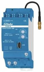
Eltako FAM14 - ELT antenna module wireless RS485 bus SMPS
| Lieske Part No. | 390405 |
|---|---|
| Mfg Part No | 30014000 |
| EAN-Code | 4010312313695 |
| Manufacturer | Eltako |
| Here only | 129,49 EUR
154,09 EUR incl. VAT
|
Further information for Eltako FAM14 - ELT antenna module wireless RS485 bus SMPS
Radio antenna module for the Eltako RS485 bus with exchangeable antenna. With included switching power supply FSNT14-12V/12W. Bidirectional. Encrypted radio. Standby loss only 0.8 watts. If required, a radio antenna FA250 or FA200 can be connected. Modular device for mounting on DIN-EN 60715 TH35 mounting rail. 1 division unit = 18mm wide, 58mm deep. Supply voltage 12V DC. Connection to the Eltako RS485 bus. Cross-wiring of bus and power supply with jumpers. The scope of delivery includes 1 switching power supply FSNT14-12V/12W, 1 spacer DS14, 2 plug-in terminating resistors with ¿, 1/2 HP, 3 jumpers 1 HP (including 1 spare), 1 jumper 1.5 HP, 2 jumpers 1/2 HP (including 1 spare) and a jumper assembly tool SMW14. If the load of the switching power supply is greater than 4W, a ventilation distance of ½ division unit must be maintained on the left side from neighboring devices. If the load is greater than 6W, an additional ventilation distance of ½ division unit is required between the FSNT14 and the FAM14 with the spacer DS14. A spacer DS14 and a long jumper are therefore included. If the total power requirement of a series 14 bus system is higher than 10W, an additional FSNT14-12V/12W must be used for every 12W of additional power requirement. Optionally, 12V DC can also be fed into the GND/+12V terminals. The FAM14 radio antenna module receives and checks all signals from the radio transmitters and repeaters in its reception area. These are passed on to downstream RS485 bus switching actuators via an RS485 interface: Up to 126 channels can be connected to the RS485 bus. Cross-wiring of bus and power supply with jumper. The enclosed second terminating resistor must be plugged into the last actuator. Up to 32 encrypted sensors can be taught in. Mini USB for connecting a PC to create a device list, to configure the actuators using the PCT14 PC tool and for data backup. A QR code for downloading the PCT14 from the Eltako homepage www.eltako.com is included with the FAM14. Gateways FGW14, FGW14-USB, FGW14W-IP and FGW14WL-IP are connected to the Hold terminal if they connect a PC with RS232 bus, up to 3 FEM wireless receiver modules with an RS485 sub-bus or LAN/WLAN with the RS484 bus. FTS14EM, FTS14TG and FWG14MS are also connected to the Hold terminal. The lower rotary switch is required for teaching in encrypted sensors and is set to AUTO 1 during operation. Unencrypted sensors do not need to be taught in the FAM14. The upper rotary switch BA can be used to set 10 different operating modes in accordance with the operating instructions. The LED at the top indicates all radio commands detected in the reception area by flashing briefly. The LED at the bottom lights up green when the PC tool PCT14 has established a connection to the FAM14. The green LED flickers when data is being read or written.The green LED goes out when the PC tool PCT14 has disconnected the connection to the FAM14.

This is an offer of:
79279 Vörstetten
https://industry-electronics.com
Tel. 07666/88499-0
Fax. 07666/88499-111
Diesen Artikel finden Sie unter:
industry-electronics.com/artikel/390405

Lieske Elektronik e.K.
Reutener Str. 1079279 Vörstetten
https://industry-electronics.com
Tel. 07666/88499-0
Fax. 07666/88499-111
Diesen Artikel finden Sie unter:
industry-electronics.com/artikel/390405