
Dold 0062409 motor brake unit BA9034N 10A
Industrial Material > Engines and accessories
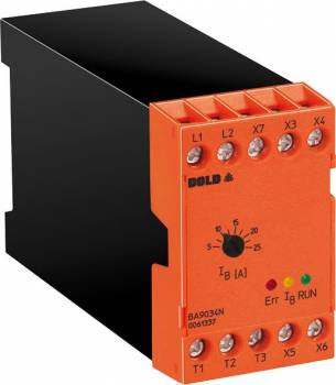
Dold 0062409 motor brake unit BA9034N 10A
| Lieske Part No. | 993718 |
|---|---|
| Mfg Part No | 0062409 |
| EAN-Code | 4030641624095 |
| Manufacturer | Dold |
| Here only | 338,95 EUR
403,35 EUR incl. VAT
|
Further information for Dold 0062409 motor brake unit BA9034N 10A
| Technical data | |
| Braking current adjustable up to max. | 32 A |
| Braking time adjustable up to max. | 31 s |
| Width | 45 mm |
| Type | BA 9034N |
| Automatic standstill monitoring | |
| Signalling output | |
| Variant | |
| Braking current | 10 A |
| Braking time | 2 - 11 s |
| Contact equipping | 1 changeover contact |
| Nominal voltage | AC 400 V |
| Approvals and Markings | UKCA |
| Variant | With standstill detection. Adjustable braking current |
Applications
The motor brake device BA9034N is suitable for a wide range of applications in industry, particularly in machine building and manufacturing technology. Typical applications include sawing machines, centrifuges, wood processing machines, textile machines, and conveyor systems. In these installations, a fast and controlled stopping of the motor is required to increase productivity and ensure safe operation. The compact design and mounting on a 35 mm standard DIN rail enable easy integration into existing installations without extensive modifications.
Functions and Equipment in Detail
The device features automatic standstill detection, ensuring that the braking function is only activated when the motor is actually at rest. This prevents unnecessary braking operations and protects the machine from excessive stress. An integrated signal output allows for the indication of operating states and fault messages. Operational readiness is indicated by a green LED, while a red LED flashes in case of faults—for example, if the network frequency is outside the tolerance range, the braking current is not reached, or there is an overtemperature in the power section. A yellow LED indicates that braking current is flowing, with the display remaining continuously lit or flashing depending on the set maximum braking time (11 s or 31 s).
Technology Explained Simply
Braking is achieved by feeding a direct current into the stator winding of the motor, generating a magnetic field that slows down the rotor. The direct voltage is generated via a single-phase rectifier, which is tapped at terminals T1 and T2. The braking delay time, i.e., the time until the residual EMF (electromotive force) is dissipated, is self-optimizing and regulated, ranging from 0.2 to 2 seconds. The supply voltage is connected at terminals L1 and L2, thereby closing the interlock contact for the motor contactor. The entire control is managed by the microcontroller, which precisely controls the braking time and braking current.
Compatibility and Accessories
The device is suitable for all single- and three-phase asynchronous motors and complies with the standard IEC/EN 60947-4-2. It is designed for use in industrial environments, with an operating temperature range of 0 °C to +45 °C and a storage temperature range of -25 °C to +75 °C. The relative humidity may reach up to 93 % at 40 °C. The operating altitude is limited to a maximum of 2000 m above sea level. The electrical life expectancy is 100,000 switching operations, and the mechanical life expectancy is 50 million switching operations. The contact configuration includes a changeover contact with a switching capacity of 5 A / AC 250 V.
Mounting and Installation
The motor brake device is mounted on a 35 mm standard DIN rail, enabling quick and secure installation. The connection terminals are clearly labeled: L1-L2 for supply voltage, T1-T2 for braking DC voltage, and X3-X4 and X5-X6 for interlocking and start. Commissioning is performed without a current meter, as the braking current and braking time settings are handled by the integrated control. The devices are wear-free and maintenance-free, reducing operating costs and increasing availability.
Operational Advantages
The shorter coast-down time increases productivity and enhances safety. The cost-effective and compact design allows for easy integration into existing installations. The automatic standstill detection and integrated fault indication ensure reliable and maintenance-free operation. Compliance with the standard IEC/EN 60947-4-2 ensures electrical safety and compatibility with other components in plant engineering. The device is designed for continuous operation and offers high reliability in industrial applications.
Approvals and Markings
The device carries the UKCA marking, confirming conformity with applicable European safety and environmental requirements. The assignment type according to IEC/EN 60947-4-1 is Type 1, meaning the device must be replaced after a short-circuit fault. The short-circuit withstand capability is up to 20 A gG / gL, and the semiconductor protection is rated for a maximum of 1200 A/2 s. The overvoltage category is III, and the creepage and clearance distances correspond to pollution degree 2 with a rated impulse withstand voltage of 6 kV.
EMC and Environmental Conditions
The device is resistant to electromagnetic interference. The immunity to static discharge is 8 kV (air discharge) according to IEC/EN 61000-4-2. The radio frequency (RF) field strength is specified as 80 MHz to 1.0 GHz at 10 V/m and 1.0 GHz to 2.5 GHz at 3 V/m according to IEC/EN 61000-4-3. The operating temperature ranges from 0 °C to +45 °C, and the storage temperature ranges from -25 °C to +75 °C. The relative humidity may reach 93 % at 40 °C. The operating altitude is limited to ≤ 2000 m.
Life Expectancy and Switching Capacity
The electrical life expectancy is 100,000 switching operations, and the mechanical life expectancy is 50 million switching operations. The switching capacity according to AC 15 is 5 A / AC 230 V for the make contact and 2 A / AC 230 V for the break contact. The power consumption of the electronics is 5 VA. The duty cycle at maximum braking current is 8 %. The braking voltage ranges from DC 10 V to DC 190 V.
Application Examples
The device is used in sawing machines, centrifuges, wood processing machines, textile machines, and conveyor systems, where a fast and safe stopping of the motor is required. The integrated standstill detection and simple mounting on the DIN rail make it a practical solution for industrial use.

This is an offer of:
79279 Vörstetten
https://industry-electronics.com
Tel. 07666/88499-0
Fax. 07666/88499-111
Diesen Artikel finden Sie unter:
industry-electronics.com/artikel/993718

Lieske Elektronik e.K.
Reutener Str. 1079279 Vörstetten
https://industry-electronics.com
Tel. 07666/88499-0
Fax. 07666/88499-111
Diesen Artikel finden Sie unter:
industry-electronics.com/artikel/993718