
Dold 0062263 RP 9800.12 voltage/frequency monitor 3/N AC400/230V
Industrial Material > Industrial relays and contactors > Switching units / measuring, control relay
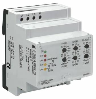
Dold 0062263 RP 9800.12 voltage/frequency monitor 3/N AC400/230V
| Lieske Part No. | 909274 |
|---|---|
| Mfg Part No | 0062263 |
| EAN-Code | 4030641622633 |
| Manufacturer | Dold |
| Here only | 319,22 EUR
379,87 EUR incl. VAT
|
Further information for Dold 0062263 RP 9800.12 voltage/frequency monitor 3/N AC400/230V
| Technical data | |
| 1- / 3-phase | 3 |
| Auxiliary voltage | Without |
| Enclosure design | Distribution board |
| Output contacts | 2 C/O contacts |
| Width | 70 mm |
| Type | RP 9800 |
| Operate delay | |
| Variant | |
| Contact equipping | 2 changeover contacts |
| Supply voltage | 3/N AC 400/230 V |
| Time delay | 90 s |
Applications
This device is primarily intended for use in self-generation plants such as photovoltaic or combined heat and power systems connected to the public low-voltage grid. It ensures compliance with VDEW guidelines for plants over 30 kVA and can be used as an alternative to disconnection points in plants under 30 kVA, provided a manual disconnection point is available. Disconnection occurs when voltage or frequency limits are exceeded or undershot, protecting grid stability.
Functions and Equipment in Detail
When a limit value is reached, the relays switch to the rest position, causing disconnection of the plant from the grid. Reconnection occurs after an adjustable delay time of 90 seconds, once measured values are again within the permissible range. Limit value settings are adjusted via detent rotary switches, enabling simple and precise adjustment. All set values are simultaneously visible, facilitating inspection and documentation. Tamper protection is ensured by a sealable transparent cover.
Technology Explained Simply
Voltage monitoring is performed 3-phase against N, evaluating the maximum and minimum values of individual phases. Frequency is measured in phase L1, with the neutral conductor serving as reference. Measurement is carried out using the RMS method, enabling accurate representation of actual voltage values. The output relays for voltage and frequency operate independently, so disconnection occurs if either parameter exceeds its limit. The 90-second delay prevents short-term fluctuations from triggering unwanted disconnection. The response delay is activated, meaning the device does not react immediately to minor deviations but includes a short stabilization period.
Compatibility and Accessories
The device is designed for a supply voltage of 3/N AC 400/230 V and requires no auxiliary voltage. It is designed for mounting in an installation distributor and complies with standards DIN EN 60255-1 and DIN EN 60947-1. The neutral conductor terminal is present in the RP 9800.12 variant and must be connected. Indication is provided via LEDs: green for power supply, red for voltage and frequency deviations, yellow for relay states. The yellow LEDs flash during the delay time tw.
Mounting and Installation
Mounting is performed in an installation distributor. The width is 70 mm, enabling standard installation in enclosures. The neutral conductor must be connected to the designated terminal. Settings are adjusted via rotary switches for voltage and frequency limit values, reconnection delay time, and 10-minute average voltage value. LED indication allows for quick visual control of the operating status.
Operational Advantages
Simple operation via detent rotary switches and simultaneous visibility of all settings facilitate configuration and maintenance. Tamper protection via the sealable cover increases security. High measurement accuracy and separate relays for voltage and frequency ensure reliable and precise response to grid disturbances. The adjustable delay time prevents unnecessary disconnections due to short-term fluctuations and ensures stable plant operation.
Frequency and Voltage Settings
Frequency monitoring is adjustable in the range of 50.2 to 52 Hz (overfrequency) and 47 to 49.8 Hz (underfrequency). Voltage monitoring covers values from 97 to 218 V (L-N) at 182 V nominal voltage and 248 to 276 V (L-N) at 230 V nominal voltage. Voltage drop settings range from 131 to 164 V (L-N) at 182 V and 166 to 207 V (L-N) at 230 V. Additionally, a 10-minute average for voltage overvoltage can be set, ranging from 189 to 211 V (L-N) at 182 V and 239 to 267 V (L-N) at 230 V. Settings are adjusted via 8-step rotary switches calibrated in percentage values of nominal voltage.
Indication and Status Monitoring
Status indication is provided via LEDs: the green LED indicates power supply. The red LED for frequency (f<>) lights up during deviations, the red LED for voltage (U<>) lights up during voltage deviations and flashes when the 10-minute average is exceeded. The yellow LEDs for relays (f<> and U<>) light up when relays are energized and flash during the delay time tw. This indication enables quick visual control of operating status and response to grid disturbances.

This is an offer of:
79279 Vörstetten
https://industry-electronics.com
Tel. 07666/88499-0
Fax. 07666/88499-111
Diesen Artikel finden Sie unter:
industry-electronics.com/artikel/909274

Lieske Elektronik e.K.
Reutener Str. 1079279 Vörstetten
https://industry-electronics.com
Tel. 07666/88499-0
Fax. 07666/88499-111
Diesen Artikel finden Sie unter:
industry-electronics.com/artikel/909274