
Dold 0061016 time relay AC/DC24V 10S
Industrial Material > Industrial relays and contactors > Industrial Timers
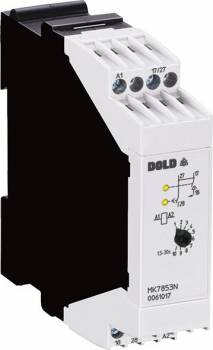
Dold 0061016 time relay AC/DC24V 10S
| Lieske Part No. | 202600 |
|---|---|
| Mfg Part No | 0061016 |
| EAN-Code | 4030641610166 |
| Manufacturer | Dold |
| Here only | 137,81 EUR
163,99 EUR incl. VAT
|
Further information for Dold 0061016 time relay AC/DC24V 10S
| Technical data | |
| Enclosure design | Switch cabinet |
| Output contacts | 1 C/O contact, 1 NO contact |
| Time function(s) | Star-Delta-Timer |
| Time range | 0,5 s - 100 s |
| Width | 22,5 mm |
| Type | MK 7853N |
| Variant | |
| Contact changeover time | 100 ms |
| Contact equipping | 1 contact fleeting on make, 1 NO contact on delay |
| Nominal voltage | AC/DC 24 V |
| Time range max. value | 10 s |
Applications
This time relay is used in systems where three-phase motors with high starting current are operated, such as in material handling, packaging industry, or pump control. The star-delta starting function enables a gentle motor acceleration, minimizing mechanical stress on the drive and electrical stress on the network. Applications are in industrial environments with an operating temperature range of -20 °C to +60 °C.
Functions and Equipment in Detail
The device features two separate output relays. Upon application of operating voltage, the first relay (for star start) is energized and remains active until the set start time (ranging from 0.5 s to 100 s) has elapsed, after which it returns to its resting position. After the defined contact switching time of 100 ms, the second relay (for delta operation) is activated and remains energized as long as the device is under voltage. The time delay is continuously adjustable on an absolute scale, with a repeat accuracy of ≤ ± 0.5 % of the scale end value. The contact configuration includes a make-before-break contact and a delayed-closing contact, enabling control of two separate contactors.
Technology Explained Simply
The star-delta function allows the motor to start initially in star configuration, reducing the starting current to approximately one-third of the rated current. After the set delay time, the motor is switched to delta configuration to achieve full torque operation. The contact switching time of 100 ms ensures a safe transition between the two switching states without interruption of current. The output contacts are rated for an operating voltage of AC 250 V, with a switching current of 3 A at AC 230 V for closing contacts. The mechanical life is 20 million operations, and the electrical life is 500,000 operations at 3 A/AC 230 V.
Compatibility and Accessories
The device is specified according to IEC/DIN EN 61812-1 and complies with standards for time relays. The terminal connections are designed for conductor cross-sections up to 2.5 mm² solid or 1.5 mm² stranded wire with sleeve and plastic collar, in accordance with DIN 46228. Optional plug-in terminal blocks are available, enabling quick device replacement. The terminals are available either as screw terminals or spring-cage terminals.
Mounting and Installation
The device is mounted in enclosures and designed for continuous operation. Mounting is in standard enclosure modules with a width of 22.5 mm. The operating temperature range is -20 °C to +60 °C, and the storage temperature range is -45 °C to +60 °C. The protection rating is IP 40 for the housing and IP 20 for the terminals, providing protection against touch and dust, but not against water. The operating altitude is limited to a maximum of 2000 m above sea level.
Operational Advantages
By limiting the starting current, the risk of tripping overcurrent protection devices is avoided. The reduced power consumption during the starting phase protects the network infrastructure and reduces thermal stress on motors. The high repeat accuracy and short reset time of 40 ms ensure reliable and precise control. Integrated yellow LEDs indicate the operating status of both relays, facilitating diagnostics during operation.
Protection Rating and Environmental Conditions
The housing is made of thermoplastic with V0 flammability rating according to UL Subj. 94, providing good flame resistance. The vibration resistance is defined by an amplitude of 0.35 mm in the frequency range of 10 to 55 Hz. The relative humidity may reach up to 93 % at 40 °C. Electromagnetic interference suppression complies with Class B limits according to EN 55011, ensuring electromagnetic compatibility (EMC).
Certifications and Standards
The device complies with IEC/DIN EN 61812-1 for time relays, IEC/EN 60947-5-1 for switching devices, IEC/EN 60529 for protection ratings (IP 40/IP 20), and IEC/EN 61000-4-2 to -6 for electromagnetic compatibility. The rated impulse voltage is 4 kV at pollution degree 2.
Terminal Designation
The terminal connections are designated as follows: A1/A2 for power supply, 17/18 for the closing contact of the star contactor, 27/28 for the closing contact of the delta contactor. The yellow LEDs indicate the operating status of both relays.
Operational Safety
Short-circuit resistance is ensured by a maximum fuse rating of 6 A gG/gL. The mechanical life is 20 million operations, and the electrical life is 500,000 operations at 3 A/AC 230 V. The reset time is 40 ms at a time delay of 50/100 s.
Climate and Environmental Resistance
The climate resistance corresponds to IEC/EN 60068-1, designation 20/060/04. The vibration resistance is defined according to IEC/EN 60068-2-6 with an amplitude of 0.35 mm.
Application Focus
The device is particularly suitable for applications requiring gentle motor start-up to avoid network loading and extend the service life of drive technology. It is used in industrial control systems, pump installations, conveyor belts, and other drive systems.

This is an offer of:
79279 Vörstetten
https://industry-electronics.com
Tel. 07666/88499-0
Fax. 07666/88499-111
Diesen Artikel finden Sie unter:
industry-electronics.com/artikel/202600

Lieske Elektronik e.K.
Reutener Str. 1079279 Vörstetten
https://industry-electronics.com
Tel. 07666/88499-0
Fax. 07666/88499-111
Diesen Artikel finden Sie unter:
industry-electronics.com/artikel/202600