
Dold 0060425 PH9270.91 semiconductor relay UH24VDC
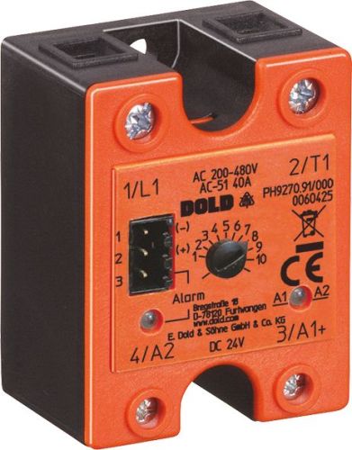
Dold 0060425 PH9270.91 semiconductor relay UH24VDC
| Lieske Part No. | 1001391 |
|---|---|
| Mfg Part No | 0060425 |
| EAN-Code | 4030641604257 |
| Manufacturer | Dold |
| Here only | 159,72 EUR
190,07 EUR incl. VAT
|
Further information for Dold 0060425 PH9270.91 semiconductor relay UH24VDC
| Technical data | |
| Load current up to | 40 A |
| Load voltage up to | AC 480 V |
| Number of poles | 1-pole |
| On/Off Input Control | DC |
| Width | 45 mm |
| Type | PH 9270 |
| Signalling output | |
| Variant | |
| Auxiliary voltage | DC 24 V |
| Load current | AC 40 A |
| Load voltage | AC 200 - 480 V |
| Semiconductor output | 1-pole |
| Variant | Switching at zero crossing. Control via A1/A2 with under- and over current monitoring and PNP transistor output with de-energized on trip. Without heat sink |
Applications
This semiconductor relay is used in the plastics and rubber industry, injection moulding machines, extruders, thermoforming and blow-moulding machines, packaging machines, soldering systems, and in the food industry. It continuously monitors the load circuit and detects faults such as load circuit interruption, over- or under-current, missing load voltage, fuse failure, or thyristor fault. This function enables rapid fault detection and localisation, increasing operational safety.
Functions and Equipment in Detail
The device features an integrated load circuit monitoring system with an adjustable load current threshold. If deviations from the set current value or a defective power semiconductor occur, an alarm output is activated. The alarm output is designed as a PNP semiconductor alarm output and operates on the rest current principle, enabling SPS-compatible signal transmission. Status indication is provided via a dual-colour LED: the LED A1/A5,1 cm ( 2 inch ) indicates the status of the control input (yellow = activated, off = not activated), while the LED "Alarm indicates the device status (green = no fault, red = fault, off = no auxiliary voltage). Monitoring occurs when auxiliary voltage is applied (A3+/A2).
Technology Explained Simply
The relay is based on two antiparallel-connected thyristors responsible for the switching function. The DCB technology (Direct-Copper-Bonding process) ensures optimal heat dissipation, reducing thermal stress and increasing lifespan. The device is supplied without a heatsink, although a version with a heatsink for DIN rail mounting is available as an option. The width is 45 mm, enabling compact installation in standard control panels. The load voltage range is AC 200 to 480 V, and the load current is up to 40 A (AC 51). Switching occurs at zero voltage, making switching operations currentless and noiseless.
Compatibility and Accessories
The semiconductor relay is compliant with IEC/EN 60947-4-3. It is designed for use in industrial control systems and can be operated compatibly with PLC systems. Control is via a digital input with DC 24 V. An optional version with a heatsink for DIN rail mounting is available, enabling improved heat dissipation. For thermal protection, a temperature limit switch (normally open) can be inserted into the designated slot on the underside; for example, the UCHIYA type UP62–100 is suitable.
Mounting and Installation
Mounting is in standard control panels with a width of 45 mm. Installation must be carried out by a qualified electrician. The connection terminals are clearly labelled: A1+/A2 for the control input, A3+/A2 for the operating voltage and load circuit monitoring, L1 for the mains connection, and T1 for the load output. Switching occurs according to the zero-voltage switching principle, with switching operations taking place at the zero crossing of voltage or current.
Operational Advantages
The device offers wear-free and noiseless switching, reducing maintenance and increasing operational safety. The integrated load circuit monitoring enables rapid fault detection, minimising downtime. The PNP alarm output logic is PLC-compatible, facilitating integration into existing control systems. The DCB technology ensures efficient heat dissipation, increasing reliability under load conditions. The width of 45 mm allows compact installation in limited space.
Protection Against Contact IP 20
The device meets the protection against contact IP 20, providing protection against contact with fingers and against solid foreign objects larger than 12.5 mm. It is intended for use in enclosed control panels.
Approvals and Markings
The device complies with standards IEC/EN 60947-4-3 and is suitable for use in industrial installations. Approvals are listed in the manufacturer’s datasheet.
Function of the Alarm Output
The alarm output is activated when a fault in the load circuit is detected, such as a broken load circuit, defective thyristor, excessive or insufficient load current, or missing mains voltage below 100 V AC. The Alarm LED indicates the fault condition (red). If auxiliary voltage (A3+/A2) is missing, the LED is off.
Maintenance and Operation
Maintenance involves visual inspection of the LED indicators and, if necessary, checking the connection terminals. The lifespan is extended by the wear-free switching technology and efficient heat dissipation.

This is an offer of:
79279 Vörstetten
https://industry-electronics.com
Tel. 07666/88499-0
Fax. 07666/88499-111
Diesen Artikel finden Sie unter:
industry-electronics.com/artikel/1001391

Lieske Elektronik e.K.
Reutener Str. 1079279 Vörstetten
https://industry-electronics.com
Tel. 07666/88499-0
Fax. 07666/88499-111
Diesen Artikel finden Sie unter:
industry-electronics.com/artikel/1001391