
Dold 0060394 standstill monitor 0.2-6s
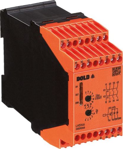
Dold 0060394 standstill monitor 0.2-6s
| Lieske Part No. | 1002231 |
|---|---|
| Mfg Part No | 0060394 |
| EAN-Code | 4030641603946 |
| Manufacturer | Dold |
| Here only | 736,56 EUR
876,51 EUR incl. VAT
|
Further information for Dold 0060394 standstill monitor 0.2-6s
| Technical data | |
| 1- / 2-channel | 2 |
| Approvals | UL |
| Cat. / PL acc. to EN ISO 13849-1 | 4/e |
| Classification | Sensorless |
| Connection | Pluggable cage clamp terminals, Pluggable screw terminals, Screw terminals |
| Forcibly guided output contacts max. | 1 NC contact, 3 NO contacts |
| Indicator contacts | 1 NO contact, 2 Semiconductor monitoring outputs |
| Measuring motor voltage max. | 690 V |
| Nominal voltage | AC, DC |
| SIL CL acc. to IEC/EN 62061 | 3 |
| SIL acc. to IEC/EN 62061 | 3 |
| Thermal current Ith max. | 5 A |
| Width | 45 mm |
| Type | LH 5946 |
| Variant | |
| Auxiliary voltage | AC 400 V |
| Contact equipping | 3 NO contacts, 1 NC contact |
| Response value | 20 - 400 mV |
| Terminal type | screw terminals fixed |
| Time range | 0,2 - 6 s |
| Approvals and Markings | UL-listed C/US, TÜV, UKCA, CCC |
Applications
The stillstand monitor is suitable for monitoring motors in industrial plants, particularly in applications where safe standstill monitoring is required, such as in conveyor technology, packaging industry, or machine building. It can also be used in systems with frequency converters, as it responds to the induced voltage, which is present even at variable speeds. The direction-independent operation allows for flexible integration into existing installations.
Functions and Equipment in Detail
The device features fail-safe safety output contacts with a configuration of 3 NO contacts and 1 NC contact, rated for AC 250 V. Additionally, it includes 2 semiconductor alarm outputs and 1 NO contact as an alarm output. The trigger voltage is adjustable in the range of 20 to 400 mV, and the standstill time can be set between 0.2 and 6 seconds. These adjustment options allow for application-specific tuning of the response time. The wire break detection in the measurement circuit provides additional safety by detecting an open conductor in the circuit and responding accordingly.
Technology Explained Simply
The stillstand monitor operates without external sensors by measuring the induced voltage in the motor during deceleration. When the motor stops, the induced voltage drops below the set threshold (minimum 20 mV), activating the output relay. The fail-safe contacts ensure that the safety function continues to operate even in the event of mechanical or electrical faults in the device. The LED indicators signal the operating status, motor standstill, and wire break in the measurement circuit, facilitating diagnosis during operation.
Compatibility and Accessories
The device is compatible with the safety mounting bracket SAFEMASTER STS, enabling an extension of safety functions. It complies with safety requirements up to Category 4 and PL e according to EN ISO 13849-1, as well as up to SIL 3 according to IEC/EN 62061. Certifications include UL-listed C/US, TÜV, UKCA, and CCC, enabling use in various markets. The connection technology includes fixed screw terminals as well as removable spring and screw terminals, allowing flexible installation with different cable types.
Mounting and Installation
Mounting is done in standard control panels with a width of 45 mm. The connection terminals are designed for secure connections, with the option of using removable spring or screw terminals depending on requirements. Commissioning requires setting the trigger voltage and standstill time, with the manufacturer’s instructions to be followed. The device indicators support checking the operating status during installation.
Advantages in Operation
The sensorless operation reduces the number of required components and lowers maintenance effort. The fast response time and direction-independent operation increase the reliability of the system. The integrated wire break detection and LED indicators improve fault diagnosis. The high safety certification up to SIL 3 and Category 4 allows use in critical applications without requiring additional safety measures. Compatibility with frequency converters extends the application range in modern drive systems.

This is an offer of:
79279 Vörstetten
https://industry-electronics.com
Tel. 07666/88499-0
Fax. 07666/88499-111
Diesen Artikel finden Sie unter:
industry-electronics.com/artikel/1002231

Lieske Elektronik e.K.
Reutener Str. 1079279 Vörstetten
https://industry-electronics.com
Tel. 07666/88499-0
Fax. 07666/88499-111
Diesen Artikel finden Sie unter:
industry-electronics.com/artikel/1002231