
Dold 0060314 GB9034/0101 200A AC50/60Hz 400V motor brake relay
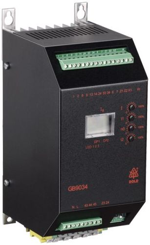
Dold 0060314 GB9034/0101 200A AC50/60Hz 400V motor brake relay
| Lieske Part No. | 1001886 |
|---|---|
| Mfg Part No | 0060314 |
| EAN-Code | 4030641603144 |
| Manufacturer | Dold |
| Here only | 2.391,63 EUR
2.846,04 EUR incl. VAT
|
Further information for Dold 0060314 GB9034/0101 200A AC50/60Hz 400V motor brake relay
| Technical data | |
| Braking current adjustable up to max. | 600 A |
| Braking time adjustable up to max. | 320 s |
| Width | 110 mm |
| Type | GB 9034 |
| Automatic standstill monitoring | |
| External brake contactor required | |
| Signalling output | |
| Temperature monitoring | |
| Variant | |
| Auxiliary voltage | Without |
| Braking current | 200 A |
| Nominal voltage | AC 400 V |
| Approvals and Markings | UKCA |
| Variant | Brake current monitoring, thermistor-motor protection input, star-delta control and output relay for standstill indication. Removable terminals |
Applications
The motor brake device is designed for drives requiring rapid and secure braking. Typical applications include machines that could become hazardous when stationary, or systems where short coast-down times are critical for productivity. The device variant includes braking current monitoring, a thermistor motor protection input, star/delta control, and a standstill indicator relay. The automatic standstill monitoring ensures that the braking process ends once the motor has stopped. In case of standstill-dependent braking, a potential-free signaling contact indicates if the motor has not come to a stop within the maximum braking time.
Functions and Equipment in Detail
The device features integrated temperature monitoring, which monitors the motor and/or heat sink condition. The control terminals are designed for plug-in connection, facilitating connection and replacement. The width is 110 mm. An external brake contactor is required, as the device does not include an integrated brake contactor for this power class. Control is performed via terminals 6–7 (start contact) and 1–2 (brake contactor). The interlock contacts 8–9 ensure that the motor contactor is switched off before the braking current flows, to avoid inductive voltage spikes. The ready LED indicates that the supply voltage is present.
Technology Explained Simply
DC braking works by applying a DC voltage to the stator winding of the motor, generating a braking torque. The single-phase rectification ensures that the current flows in one direction, creating a continuous braking torque. The braking time is controlled by a timer, which switches off the braking current after the set time has elapsed. The safety time interval between switching off the motor contactor and switching on the brake contactor prevents inductive voltages from damaging the power section. Standstill detection monitors the motor condition and switches off the braking current as soon as the motor stops.
Compatibility and Accessories
The device is suitable for all asynchronous motors and can be integrated into existing installations. It is specified according to IEC/EN 60947-4-2. The variant includes a thermistor motor protection input, which can be optionally used to protect the motor from overheating. The star/delta control enables a smooth motor start-up. Standstill monitoring is integrated and can signal via an output contact if the motor does not stop within the specified time. The UKCA approval is available.
Mounting and Installation
Mounting is carried out in an enclosure. The supply voltage is connected to terminals L1–L2. Motor connections are made to U, V, W. The external brake contactor is controlled via terminals 1–2. The interlock contacts 8–9 secure the sequence of switching operations. The connection terminals are plug-in type, facilitating installation and maintenance. The width of 110 mm allows for compact installation.
Advantages in Operation
The device offers higher safety through reliable braking and shorter coast-down times, increasing productivity. It is wear-free and maintenance-free, reducing operating costs. The simple installation into existing systems reduces installation effort. The adjustable parameters for braking current and time allow adaptation to different drive requirements. The integrated standstill monitoring and signaling output increase operational safety.

This is an offer of:
79279 Vörstetten
https://industry-electronics.com
Tel. 07666/88499-0
Fax. 07666/88499-111
Diesen Artikel finden Sie unter:
industry-electronics.com/artikel/1001886

Lieske Elektronik e.K.
Reutener Str. 1079279 Vörstetten
https://industry-electronics.com
Tel. 07666/88499-0
Fax. 07666/88499-111
Diesen Artikel finden Sie unter:
industry-electronics.com/artikel/1001886