
Dold 0059576 reversing contactor BH9255.11/61 UH AC/DC24V 4A
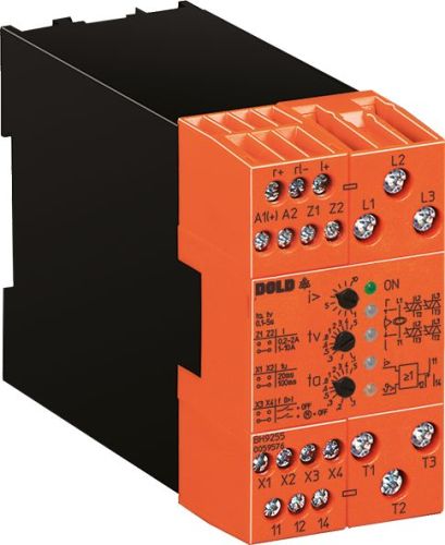
Dold 0059576 reversing contactor BH9255.11/61 UH AC/DC24V 4A
| Lieske Part No. | 1153840 |
|---|---|
| Mfg Part No | 0059576 |
| EAN-Code | 4030641595760 |
| Manufacturer | Dold |
| Here only | 506,27 EUR
602,46 EUR incl. VAT
|
Further information for Dold 0059576 reversing contactor BH9255.11/61 UH AC/DC24V 4A
| Technical data | |
| Approvals | UL |
| Enclosure design | Switch cabinet |
| Load current up to | 20 A |
| Load voltage up to | 3AC 24 - 480 V |
| Number of poles | 3-pole |
| On/Off Input Control | AC/DC, DC |
| Width | 45 mm, 67,5 mm, 112,5 mm |
| Type | BH 9255 |
| Signalling output | |
| Temperature monitoring | |
| Variant | |
| Auxiliary voltage | AC/DC 24 V |
| Contact equipping | 1 changeover contact |
| Control input | AC/DC 24 - 80 V r+/rl-/l+ |
| Rated continuous current | 4 A |
| Approvals and Markings | UL-listed C/US |
Applications
This reversing contactor is designed for use in industrial drive systems where safe and reliable switching of rotation direction is required. It is suitable for applications such as conveyor systems, machine tools, pumps, or fans, where the motor must operate in both directions. The integrated current monitoring enables protection of the motor against overload, with current in phase L1 being monitored. If a set threshold is exceeded, the device can switch off the motor to prevent damage.
Functions and equipment in detail
The device features an electrical interlock that prevents simultaneous actuation of both rotation directions. This ensures safe operation and prevents short circuits or mechanical stress. Control is achieved via a control input with AC/DC 24–80 V, using signals r+ (clockwise), rl- (reverse), and l+ (counter-clockwise). An auxiliary voltage input (AC/DC 24 V) supplies the control and monitoring electronics. The rated continuous current is 4 A, with the device designed for load currents up to 20 A. The load voltage can reach up to 3AC 24–480 V.
Technology explained simply
The power electronics of the BH9255 are based on semiconductor technology and enable zero-voltage switching, which increases component lifespan and minimizes electromagnetic interference. The integrated temperature monitoring protects the power semiconductors against overheating, for example during frequent reversing. If an overtemperature is detected, the semiconductors switch off and the release contact (11–14) returns to its resting position. This state is stored and can be reset by briefly switching off and then back on the control. The switching pause tu is set via a bridge between X3 and X4 and is either 20 or 100 ms, to avoid mechanical stress during reversing.
Compatibility and accessories
The device complies with IEC/EN 60947-1 and IEC/EN 60947-4-2 standards and carries the UL-listed C/US approval. Galvanic isolation between the control and main current circuits increases safety. Control is via digital inputs (AC/DC, DC), with functions parameterized via bridges (X1–X2, X3–X4). The X3–X4 bridge allows additional motor switching off when the release contact is switched, which is advantageous for manual control. Status indication is provided by LEDs: a green LED indicates the presence of auxiliary voltage, yellow LEDs indicate active rotation direction (r, l), and red LEDs (i> and ϑ>) indicate overload or overtemperature.
Mounting and installation
The reversing contactor is mounted in enclosures and is designed for installation in standard control panels. Connections are clearly labeled: A1/A2 for auxiliary voltage, r+/rl- and l+/rl- for control inputs, Z1/Z2, X1/X2, X3/X4 for parameterization, L1/L2/L3 for mains connection, and T1/T2/T3 for motor connection. Contacts 11, 12, 14 serve as output relays for release and signaling functions. Mounting is done via screw terminals, designed for the respective conductor cross-sections.
Advantages in operation
The device offers short switching-on and switching-off times, increasing responsiveness during operation. The integrated current and temperature monitoring ensures a high level of protection for both motor and device. Galvanic isolation and zero-voltage switching technology enhance operational safety. LED indicators allow quick visual diagnosis of the operating status. Parameterization via bridges allows flexible adaptation to different applications, especially for manual or PLC-controlled operation.

This is an offer of:
79279 Vörstetten
https://industry-electronics.com
Tel. 07666/88499-0
Fax. 07666/88499-111
Diesen Artikel finden Sie unter:
industry-electronics.com/artikel/1153840

Lieske Elektronik e.K.
Reutener Str. 1079279 Vörstetten
https://industry-electronics.com
Tel. 07666/88499-0
Fax. 07666/88499-111
Diesen Artikel finden Sie unter:
industry-electronics.com/artikel/1153840