
Dold 0059267 standstill monitor 20-400mV UH AC230V
Industrial Material > Industrial relays and contactors > Switching units / measuring, control relay
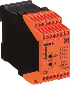
Dold 0059267 standstill monitor 20-400mV UH AC230V
| Lieske Part No. | 1324766 |
|---|---|
| Mfg Part No | 0059267 |
| EAN-Code | 4030641592677 |
| Manufacturer | Dold |
| Here only | 736,56 EUR
876,51 EUR incl. VAT
|
Further information for Dold 0059267 standstill monitor 20-400mV UH AC230V
| Technical data | |
| 1- / 2-channel | 2 |
| Approvals | UL |
| Cat. / PL acc. to EN ISO 13849-1 | 4/e |
| Classification | Sensorless |
| Connection | Pluggable cage clamp terminals, Pluggable screw terminals, Screw terminals |
| Forcibly guided output contacts max. | 1 NC contact, 3 NO contacts |
| Indicator contacts | 1 NO contact, 2 Semiconductor monitoring outputs |
| Measuring motor voltage max. | 690 V |
| Nominal voltage | AC, DC |
| SIL CL acc. to IEC/EN 62061 | 3 |
| SIL acc. to IEC/EN 62061 | 3 |
| Thermal current Ith max. | 5 A |
| Width | 45 mm |
| Type | LH 5946 |
| Variant | |
| Auxiliary voltage | AC 230 V |
| Contact equipping | 3 NO contacts, 1 NC contact |
| Response value | 20 - 400 mV |
| Terminal type | screw terminals fixed |
| Time range | 0,2 - 6 s |
| Approvals and Markings | UL-listed C/US, TÜV, UKCA, CCC |
Stillstandswächter is the central product type described here. The device operates without external sensors such as encoders or proximity switches, simplifying installation and reducing maintenance. The functionality is based on measuring the induced voltage, which decreases as the motor slows down. When this voltage falls below the set threshold, standstill is detected. Detection is independent of motor rotation direction, expanding application possibilities.
Sensorless is a key feature that simplifies installation and maintenance. Since no additional sensors are required, costs and effort for mounting and calibration are eliminated. Wire break detection in the measurement circuit ensures that interruptions in the motor connection or measurement circuit are detected, increasing the reliability of monitoring. Indication is provided via LED indicators for motor standstill, wire break, and operating voltage, visually signaling the operational status.
Zwangsgeführte Ausgangskontakte are a central component of the safety function. The device features 3 normally closed contacts and 1 normally open contact, rated for a maximum operating voltage of AC 250 V. These contacts are forced-guided, meaning they are mechanically designed to switch only in a defined state, preventing false alarms or malfunctions. The contacts are rated for a thermal current of up to 5 A.
Sicherheitszulassungen are essential for use in safety-critical applications. The device complies with Category 4 and Performance Level e according to EN ISO 13849-1, representing the highest safety level for safety functions in industry. Additionally, it meets requirements up to SIL 3 according to IEC/EN 62061, confirming suitability for safety-critical applications in automation technology. Certifications include UL-listed C/US, TÜV, UKCA, and CCC, ensuring international usability.
Anschlusstechnik is via fixed screw terminals, ensuring a secure and durable connection. The terminals are designed for mounting in an enclosure and allow for easy wiring. The width is 45 mm, enabling compact installation in standard control panels. The device is designed for an auxiliary voltage of AC 230 V, supplied via the network power supply system.
Kompatibilität includes use with frequency inverters, enabling integration into modern drive systems. The measured motor voltage can reach up to 690 V, allowing use with high-voltage motors. The device can be combined with safety interlocks such as SAFEMASTER STS to integrate additional safety functions. The alarm contacts consist of one normally closed contact and two semiconductor alarm outputs, which can be used for signaling to higher-level controls or operator panels.
Betrieb und Wartung are simplified by easy retrofitting and sensorless operation. Voltage threshold and standstill time settings are adjusted via the device surface, with LED indicators visually signaling the operational status. The device description and operating manual include instructions for commissioning and setup to ensure correct configuration. The devices are designed for industrial environments and meet requirements for safety and reliability.
Einsatzbereiche include monitoring motors in production systems, conveyor systems, pumps, fans, and other drive systems where safe shutdown is required. Direction-independent detection and compatibility with frequency inverters make the device particularly suitable for modern, flexible drive systems. Certifications according to EN ISO 13849-1 and IEC/EN 62061 enable use in safety-critical applications where reliability of standstill detection is crucial.
Vorteile im Betrieb include reduced maintenance costs due to sensorless operation, fast response time, and easy integration into existing systems. LED indicators allow quick diagnosis of operational status, and wire break detection increases monitoring reliability. Compatibility with safety interlocks extends functionality and allows flexible adaptation to the requirements of the respective system.
Technik verständlich erklärt is based on measuring the induced voltage in the motor. When the motor stops, the induced voltage drops to a value below the set threshold, triggering standstill detection. The forced-guided contacts ensure that output signals are transmitted safely and reliably. The adjustability of voltage threshold and standstill time allows adaptation to different motor and system conditions. The semiconductor alarm outputs and normally closed contact are used for signaling to higher-level controls.
Kompatibilität und Zubehör includes use with frequency inverters and compatibility with safety interlocks such as SAFEMASTER STS. The alarm contacts consist of one normally closed contact and two semiconductor alarm outputs, which can be used for signaling to controls or operator panels. The devices are designed for an auxiliary voltage of AC 230 V, supplied via the network power supply system.
Montage und Installation are carried out in an enclosure with a width of 45 mm. Connection is via fixed screw terminals, ensuring a secure connection. Commissioning and setup are performed via the device surface, with LED indicators visually signaling the operational status. The device description and operating manual include instructions for correct configuration.
Vorteile im Betrieb include reduced maintenance costs due to sensorless operation, fast response time, and easy integration into existing systems. LED indicators allow quick diagnosis of operational status, and wire break detection increases monitoring reliability. Compatibility with safety interlocks extends functionality and allows flexible adaptation to the requirements of the respective system.

This is an offer of:
79279 Vörstetten
https://industry-electronics.com
Tel. 07666/88499-0
Fax. 07666/88499-111
Diesen Artikel finden Sie unter:
industry-electronics.com/artikel/1324766

Lieske Elektronik e.K.
Reutener Str. 1079279 Vörstetten
https://industry-electronics.com
Tel. 07666/88499-0
Fax. 07666/88499-111
Diesen Artikel finden Sie unter:
industry-electronics.com/artikel/1324766