
Dold 0059228 IL5881.12 DC24-500V UH AC220-240V insulation monitor 20-500 kΩ
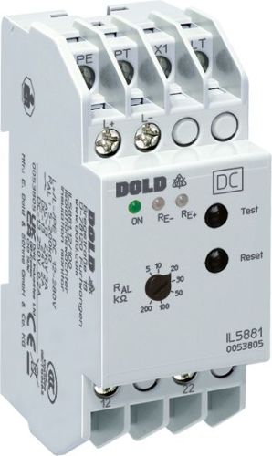
Dold 0059228 IL5881.12 DC24-500V UH AC220-240V insulation monitor 20-500 kΩ
| Lieske Part No. | 1001709 |
|---|---|
| Mfg Part No | 0059228 |
| EAN-Code | 4030641592288 |
| Manufacturer | Dold |
| Here only | 255,83 EUR
304,44 EUR incl. VAT
|
Further information for Dold 0059228 IL5881.12 DC24-500V UH AC220-240V insulation monitor 20-500 kΩ
| Technical data | |
| Enclosure design | Distribution board |
| IMD type | DC |
| Nominal voltage IT system | DC 12 - 280 V, DC 24 - 500 V |
| Response value | 5 - 500 kΩ |
| Response value type | Adjustable |
| Width | 35 mm |
| Type | IL 5881 |
| Earth fault indicator | |
| Variant | |
| Alarm value | 20 - 500 kOhm |
| Auxiliary voltage | AC 220 - 240 V |
| Contact equipping | 2 changeover contacts |
| Nominal voltage | DC 24 - 500 V |
| Time delay | without |
| Approvals and Markings | UKCA, CCC |
Applications
The isolation monitor is specifically designed for pure DC networks operating in the range of DC 24 to 500 V. It serves a preventive fire and plant protection function by triggering a warning as soon as the insulation resistance drops, before a dangerous earth fault occurs. Applications include industrial plants, vehicles, or railway systems where IT systems are used for power supply.
Functions and Equipment in Detail
The device features two changeover contacts as output contacts, which drop out in the event of a fault (rest current principle). The trip threshold for earth fault is adjustable via a potentiometer on the front of the device and ranges from 5 to 500 kΩ. Indication is provided via LEDs: a green LED indicates operational readiness, while red LEDs (RE+ and RE−) light up in the event of an earth fault on L+ or L−. Selective earth fault detection enables quick fault localization, as the affected line (L+ or L−) can be directly identified by the illuminated LED.
Technology Explained Simply
The isolation monitor monitors the asymmetric insulation resistance between conductors L+ and L− relative to earth. When the resistance falls below the set alarm threshold, the fault is indicated via the LEDs and output relays. Programming is done via a bridge between terminals LT and X1: if the bridge is present, the device automatically resets when insulation improves (hysteresis behavior). Without the bridge, the fault condition is stored until reset via the internal or external reset button. The test button enables simulation of an earth fault for functional testing.
Compatibility and Accessories
The device is manufactured in the IL 5881 form factor, featuring a depth of 61 mm and bottom-mounted terminals. It is designed for DIN rail or screw mounting. Terminals A1 and A2 are for connection to the monitored IT system, PE is the protective earth connection. External test and reset buttons can be connected via terminals PT/X1 and LT/X1. Compliance is in accordance with IEC/EN 61557-8.
Mounting and Installation
Mounting is carried out in installation or industrial distributors according to DIN 43880. The depth of 61 mm and width of 35 mm allow for a compact installation. The terminals are located at the bottom, ensuring easy wiring. The auxiliary voltage is supplied via AC 220–240 V, requiring a separate power supply.
Advantages in Operation
The adjustable alarm threshold and selective fault indication allow the operator to monitor insulation status precisely. The hysteresis function prevents unnecessary alarms during short-term fluctuations. Integrated test and reset buttons, along with the option for external control, increase operational flexibility. The UKCA and CCC certifications confirm compliance with European and Chinese safety standards. The device is designed for use in IT systems with DC 24–500 V, with a measurement range of 20–500 kΩ.

This is an offer of:
79279 Vörstetten
https://industry-electronics.com
Tel. 07666/88499-0
Fax. 07666/88499-111
Diesen Artikel finden Sie unter:
industry-electronics.com/artikel/1001709

Lieske Elektronik e.K.
Reutener Str. 1079279 Vörstetten
https://industry-electronics.com
Tel. 07666/88499-0
Fax. 07666/88499-111
Diesen Artikel finden Sie unter:
industry-electronics.com/artikel/1001709