
Dold 0058925 BH9098.90/011 3AC100-760V AC40A load converter UH=DC24V
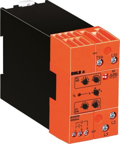
Dold 0058925 BH9098.90/011 3AC100-760V AC40A load converter UH=DC24V
| Lieske Part No. | 1000837 |
|---|---|
| Mfg Part No | 0058925 |
| EAN-Code | 4030641589257 |
| Manufacturer | Dold |
| Here only | 449,84 EUR
535,31 EUR incl. VAT
|
Further information for Dold 0058925 BH9098.90/011 3AC100-760V AC40A load converter UH=DC24V
| Technical data | |
| 1- / 3-phase | 1, 3 |
| Enclosure design | Switch cabinet |
| Measuring range max. | 40 A (37 kW) |
| Width | 45 mm |
| Type | BH 9098 |
| Variant | |
| Auxiliary voltage | DC 24 V |
| Nominal current max | AC 40 A |
| Nominal voltage | 3AC 100 - 760 V |
| Variant | 3-phase with auxiliary voltage |
Applications
The load transducer is intended for use in industrial plants, particularly for electrical consumers with variable load, such as motors. It is designed for motors up to 22 kW at 400 V and up to 37 kW at 690 V. Measurement is performed according to the principle of active power measurement, with the application designed for symmetrical loading of the three phases, as is typical for motor loads. The device is suitable for single-phase and three-phase loads, with the three-phase variant equipped with auxiliary voltage.
Functions and Equipment in Detail
The device provides load-dependent, galvanically isolated analog signals, which can be configured as either 0 ... 20 mA and 0 ... 10 V or 4 ... 20 mA and 2 ... 10 V. The characteristic curve setting is done via two rotary switches P1 and P2, which define the endpoints of the load characteristic curve in watts as absolute values. Between these values, a proportional output signal curve is generated; outside these values, the signal remains constant. A DIP switch allows the selection of four different load characteristic curves, including one positive and one negative curve. The start-up bypass time ta is adjustable to bridge short-term load peaks during motor start-up.
Technology Explained Simply
The load transducer measures active power via a single-phase measurement connection, based on symmetrical load distribution across the three phases. The measurement voltage range is 3AC 100 to 760 V, and the auxiliary voltage is DC 24 V. The maximum rated current is AC 40 A, with the measurement range up to 40 A without an external current transformer. Input resistances range from 300 kΩ to 500 kΩ, and the internal resistance at the current connections i-k is maximum 1 mΩ. The frequency range coverage extends from 10 to 400 Hz. Measurement accuracy is ±5 % at rated load, and harmonic distortion is below 40 %. The LED indicator signals the operating status: steady light indicates that the mains voltage is present, flashing indicates the start-up bypass time. In case of faults, such as missing measurement voltage or reverse power, the LED flashes rapidly.
Compatibility and Accessories
The device is designed for use in enclosures and complies with the standard IEC/EN 60255-1. It is suitable for single-phase and three-phase loads, with the three-phase variant configured with auxiliary voltage. The width is 45 mm, enabling compact mounting in standard enclosures. The output signals are galvanically isolated and can be connected directly to control or regulation devices. Settings are made via mechanical rotary switches and a DIP switch, without requiring additional software or external devices.
Mounting and Installation
Mounting is done in an enclosure, with the 45 mm width enabling standard installation. Connections for measurement voltage and measurement current are clearly marked. The auxiliary voltage is supplied via DC 24 V. Settings for P1 and P2, as well as the start-up bypass time ta, are adjusted on-site using the mechanical switches. The LED indicator serves for visual monitoring of the operating status. Wiring is reduced, as the output signals can be connected directly to control or regulation devices.
Advantages in Operation
The load transducer enables continuous monitoring of active power consumption, supporting early detection of impending failures and enabling preventive maintenance. The galvanic isolation of the output signals increases safety and prevents network disturbances. The compact design with a 45 mm width and simple adjustment via rotary switches and a DIP switch reduces installation and maintenance effort. The application in industrial plants with variable load, such as motors, is optimized by the adjustable characteristic curve and the start-up bypass time.

This is an offer of:
79279 Vörstetten
https://industry-electronics.com
Tel. 07666/88499-0
Fax. 07666/88499-111
Diesen Artikel finden Sie unter:
industry-electronics.com/artikel/1000837

Lieske Elektronik e.K.
Reutener Str. 1079279 Vörstetten
https://industry-electronics.com
Tel. 07666/88499-0
Fax. 07666/88499-111
Diesen Artikel finden Sie unter:
industry-electronics.com/artikel/1000837