
Dold 0058753 semiconductor contactor AC230-480V AC25A
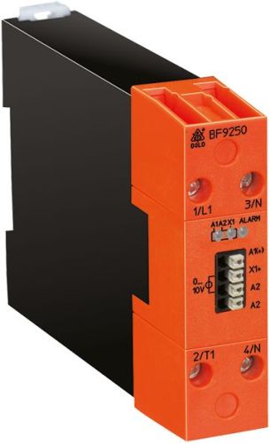
Dold 0058753 semiconductor contactor AC230-480V AC25A
| Lieske Part No. | 1001522 |
|---|---|
| Mfg Part No | 0058753 |
| EAN-Code | 4030641587536 |
| Manufacturer | Dold |
| Here only | 235,00 EUR
279,65 EUR incl. VAT
|
Further information for Dold 0058753 semiconductor contactor AC230-480V AC25A
| Technical data | |
| Analog Input Control | 4 - 20 mA |
| Approvals | UL |
| Load current up to | 50 A |
| Load voltage up to | AC 480 V |
| Number of poles | 1-pole |
| Width | 22,5 mm, 45 mm, 90 mm |
| Type | BF 9250/0_2 |
| Temperature monitoring | |
| Variant | |
| Auxiliary voltage | AC/DC 24 V |
| Contact equipping | without signal contact |
| Control input | DC 0 - 10 V |
| Load current | AC 25 A |
| Load voltage | AC 230 - 480 V |
| Semiconductor output | 1-pole |
| Approvals and Markings | UL-listed C/US |
| Variant | Output control with fixed period of 64 cycles |
Applications
This semiconductor contactor is specifically designed for controlling ohmic loads such as heaters, heating rods or infrared lamps. It is suitable for applications requiring precise temperature control, for example in process industry, food processing or plastic processing. The pulse packet control enables fine adjustment of power consumption, achieving even temperature distribution and reducing temperature fluctuations. The zero-voltage switching function ensures disturbance-free switching and minimises electrical interference in the network.
Functions and equipment in detail
The device features a control input for DC 0 to 10 V, with the option of control via DC 4 to 20 mA or a potentiometer resistance of 0 to 10 kΩ. Inverted analog inputs can also be used. Control is performed via a linear distribution of pulses over 64 cycles, enabling a high resolution of 1.5625 %. The output power can thus be varied in small steps from 0 to 100 %. LED indicators signal the operating status: green LED for auxiliary voltage, yellow LED for output status, and red LED for alarms. In case of synchronisation errors, control input faults or overtemperature of the power semiconductors, the LEDs light up accordingly, with the overtemperature message being stored and requiring a brief power-off to reset.
Technology explained simply
The semiconductor contactor operates as a zero-voltage switch, i.e. it switches the load only at the moment of zero crossing of the alternating voltage to avoid electrical interference. The varistor protection circuit protects the device against overvoltages. The temperature protection function of the power semiconductors reduces the load current when the temperature exceeds 40 °C to prevent overheating. The current reduction is linear: 0.2 A/°C at 10 A, 0.4 A/°C at 25 A, and 0.6 A/°C at 50 A. The maximum blocking voltage is ±1200 V, and the residual current in the switched-off state is 1.0 mA at a maximum junction temperature of 125 °C.
Compatibility and accessories
The device is designed for loads in the range of AC 230 to 480 V and up to 50 A. It is compatible with a control input for DC 0 to 10 V, DC 4 to 20 mA, or a potentiometer from 0 to 10 kΩ. Control is via an analog input, making it ideal for use with process control systems or PLC systems. Certifications include UL-listed C/US, enabling use in North America. It is suitable for use in environments with up to 75 % humidity (without condensation) and an operating temperature of 0 to 40 °C.
Mounting and installation
The semiconductor contactor is mountable on DIN rail and can be installed in enclosures or control cabinets. Recommended clearances to the surroundings are 20 mm above and below, and 10 mm to the left and right, to ensure sufficient cooling. The connection terminals are clearly labelled: A1 (+) and A2 for auxiliary voltage, X1 for control input, L1/N for mains connections, and T1/N for load output. Installation is carried out in accordance with standards IEC/EN 60947-4-2 and IEC/EN 60947-4-3.
Advantages in operation
The device offers high operational safety through integrated protection functions such as varistor protection, temperature protection and overcurrent protection. The LED indicators enable quick diagnosis of operating conditions and faults. The pulse packet control ensures precise and even power regulation, extending the service life of heating elements and improving energy efficiency. The zero-voltage switching minimises network interference, which is particularly important in sensitive installations. Mounting on DIN rail facilitates integration into existing control systems.

This is an offer of:
79279 Vörstetten
https://industry-electronics.com
Tel. 07666/88499-0
Fax. 07666/88499-111
Diesen Artikel finden Sie unter:
industry-electronics.com/artikel/1001522

Lieske Elektronik e.K.
Reutener Str. 1079279 Vörstetten
https://industry-electronics.com
Tel. 07666/88499-0
Fax. 07666/88499-111
Diesen Artikel finden Sie unter:
industry-electronics.com/artikel/1001522