
Dold 0058460 BN9034/1000 25A motor brake unit 15s
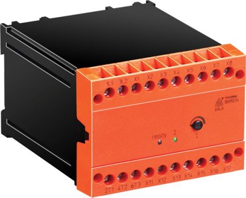
Dold 0058460 BN9034/1000 25A motor brake unit 15s
| Lieske Part No. | 1001891 |
|---|---|
| Mfg Part No | 0058460 |
| EAN-Code | 4030641584603 |
| Manufacturer | Dold |
| Here only | 637,56 EUR
758,70 EUR incl. VAT
|
Further information for Dold 0058460 BN9034/1000 25A motor brake unit 15s
| Technical data | |
| Braking current adjustable up to max. | 25 A |
| Braking time adjustable up to max. | 15 s |
| Width | 100 mm |
| Type | BN 9034 |
| Automatic standstill monitoring | |
| Signalling output | |
| Temperature monitoring | |
| Variant | |
| Auxiliary voltage | AC 230 V |
| Braking current | 25 A |
| Braking time | 15 s |
| Nominal voltage | AC 575 V |
| Approvals and Markings | UKCA |
| Variant | Wide voltage input (UN = 200...575 V) |
Applications
The motor brake device is used in industrial plants with drives requiring controlled and rapid braking. This includes, for example, sawmills, centrifuges, woodworking machines, textile machines, and conveyor systems. The application is particularly relevant in systems where a long coast-down time of the motor would be undesirable or dangerous, such as in production lines or machines with moving parts.
Functions and Equipment in Detail
The device operates with direct current braking via a single-phase rectifier and enables a maximum adjustable braking current of 25 A. The braking time is also adjustable and can last up to 15 seconds. Braking is activated by the integrated brake contactor, which is switched on after the motor contactor is de-energized and after a safety time has elapsed. The DC braking voltage is applied to the stator winding of the motor via terminals T1 and T2. The functions are coordinated so that the motor is braked after the set braking time or upon detection of standstill.
Technology Explained Simply
Braking is achieved by applying a DC voltage to the stator winding of the motor, generating a magnetic field that forces the rotor against its direction of rotation. This results in rapid braking without mechanical wear. The automatic standstill monitoring checks whether the motor has come to a stop within the maximum braking time. If standstill is not reached, a fault signal is triggered via a potential-free alarm contact. Temperature monitoring allows integration of a thermistor to protect the motor from overheating.
Compatibility and Accessories
The device is designed for rated voltages in the range of AC 200 to 575 V and complies with the standard IEC/EN 60947-4-2. The auxiliary voltage is AC 230 V. It is suitable for use in systems with an operating voltage of AC 400 V ± 10 %, with the wide-voltage version (200–575 V) optionally available. The connection terminals are designed for a maximum cross-section of 2.5 mm² per terminal. The device is designed for mounting on a 35 mm standard rail.
Mounting and Installation
Installation is carried out by clipping onto a 35 mm DIN rail. The supply voltage is connected to terminals L1 and L2, with the interlock contact closing for the motor contactor. The start function is activated via the ON button, where the DC braking voltage is supplied to the motor via T1 and T2. The ready LED indicates that the supply voltage is present. Terminals X3 and X4 are live, so care must be taken during cable routing to ensure safety against contact.
Operational Advantages
The wear-free braking increases the service life of the system and reduces maintenance. The shorter coast-down time improves safety and cost-efficiency, especially in production environments. Easy integration into existing systems allows for quick conversion without extensive modifications. Adjustable parameters for braking current and time, along with integrated standstill and temperature monitoring, enhance operational reliability.
Approvals and Markings
The device carries the UKCA marking, confirming compliance with applicable European safety and operational safety requirements. The operating temperature range is between 0 °C and +45 °C, and the storage temperature range is between -25 °C and +75 °C. The device is equipped with a protection rating of IP 20, providing protection against finger contact and vertical dripping water. The overvoltage category is III, and the pollution degree is 2.
Device Indication
The ready" LED lights up when the supply voltage is present and blinks if the braking current is set too high. The "I LED lights up when braking current is flowing. These indicators support visual monitoring of the operating status.
Width and Mounting
The device width is 100 mm, enabling compact mounting on the DIN rail. The maximum rated power of the motor is 5.5 kW at 400 V operating voltage. The electronic power consumption is 6 VA. The contacts are rated for 6 A / 250 V AC and 6 A / 30 V DC. The maximum continuous duty (ED) at maximum braking current is 8 %. The I²t value of the power semiconductor is 1250 A²s, and the inrush current value (Type 1) is 20 A.
Connection Terminals
The terminal designations include supply voltage (L1, L2), motor connections (T1, T2, T3), auxiliary voltage (X1, X2), start contact (X3, X4), interlock for motor contactor (X5, X6), fault signal (X7, X8), control for star-delta contactor (X11, X12, X12, X13), and standstill signal (X16, X17). Terminals X14 and X15 are optionally used for connecting a motor PTC protection.
Approvals and Markings
The device carries the UKCA marking, confirming compliance with applicable European safety and operational safety requirements. The operating temperature range is between 0 °C and +45 °C, and the storage temperature range is between -25 °C and +75 °C. The device is equipped with a protection rating of IP 20, providing protection against finger contact and vertical dripping water. The overvoltage category is III, and the pollution degree is 2.
Device Indication
The ready" LED lights up when the supply voltage is present and blinks if the braking current is set too high. The "I LED lights up when braking current is flowing. These indicators support visual monitoring of the operating status.
Width and Mounting
The device width is 100 mm, enabling compact mounting on the DIN rail. The maximum rated power of the motor is 5.5 kW at 400 V operating voltage. The electronic power consumption is 6 VA. The contacts are rated for 6 A / 250 V AC and 6 A / 30 V DC. The maximum continuous duty (ED) at maximum braking current is 8 %. The I²t value of the power semiconductor is 1250 A²s, and the inrush current value (Type 1) is 20 A.
Connection Terminals
The terminal designations include supply voltage (L1, L2), motor connections (T1, T2, T3), auxiliary voltage (X1, X2), start contact (X3, X4), interlock for motor contactor (X5, X6), fault signal (X7, X8), control for star-delta contactor (X11, X12, X12, X13), and standstill signal (X16, X17). Terminals X14 and X15 are optionally used for connecting a motor PTC protection.

This is an offer of:
79279 Vörstetten
https://industry-electronics.com
Tel. 07666/88499-0
Fax. 07666/88499-111
Diesen Artikel finden Sie unter:
industry-electronics.com/artikel/1001891

Lieske Elektronik e.K.
Reutener Str. 1079279 Vörstetten
https://industry-electronics.com
Tel. 07666/88499-0
Fax. 07666/88499-111
Diesen Artikel finden Sie unter:
industry-electronics.com/artikel/1001891