
Dold 0058274 IN9017/200 phase controller 0-10V AC230V 300W
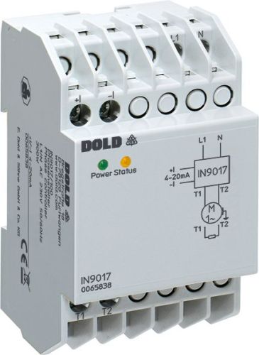
Dold 0058274 IN9017/200 phase controller 0-10V AC230V 300W
| Lieske Part No. | 1002072 |
|---|---|
| Mfg Part No | 0058274 |
| EAN-Code | 4030641582746 |
| Manufacturer | Dold |
| Here only | 325,74 EUR
387,63 EUR incl. VAT
|
Further information for Dold 0058274 IN9017/200 phase controller 0-10V AC230V 300W
| Technical data | |
| 1- / 3-phase | 1 |
| Enclosure design | Distribution board |
| Nominal load up to | 0,3 kW |
| Width | 53 mm |
| Type | IN 9017 |
| External start signal | |
| Temperature monitoring | |
| Variant | |
| Control input | 0 - 10 V |
| Mains / motor voltage | AC 230 V |
| Nominal motor power | 300 W |
| Variant | With voltage interface 0 ... 10 V |
Applications
The phase controller is suitable for various load types, including resistive loads, infrared heaters, fans, and compressors. The continuous control of output voltage allows flexible adjustment of power according to the respective operating condition, for example, for temperature control in heating systems or speed control of motors. The radio interference suppression according to limit class B ensures low electromagnetic interference, making it suitable for applications in electronically sensitive environments.
Functions and Equipment in Detail
The device features a control input with a voltage interface of 0 to 10 V, allowing the output voltage to be continuously adjusted from AC 40 V to AC 230 V. Control is achieved via phase cutting, where the output voltage varies proportionally to the input voltage. An external start signal can be connected to initiate operation via an external signal. Temperature monitoring ensures safe operation by switching off the device in case of overheating.
Technology Explained Simply
The phase controller operates on the principle of phase cutting, where the voltage wave at the output is modulated by shifting the switching-on point in time. The earlier the switching-on point, the higher the effective output voltage. Control is performed via the 0-10 V input, where 0 V corresponds to the minimum and 10 V to the maximum output voltage. The input impedance is 50 kΩ, ensuring high load independence. The re-arming time is 200 ms, indicating the speed of response to control signals. The device’s power consumption is 1.4 VA.
Compatibility and Accessories
The phase controller is designed for a mains voltage of AC 230 V ±10 % and a nominal frequency of 50/60 Hz. It is designed for continuous operation and can be used in environments with an operating temperature of 0 to +55 °C. For protection of the power semiconductor against short circuit or earth fault, a semiconductor fuse with a maximum rating of 340 A/2 s is required. The device must not be operated with capacitive loads, as this may cause malfunction.
Mounting and Installation
The device is designed as an installation distributor and can be mounted in standard switchboards with a width of 53 mm. Connections are made via terminals, with the supply voltage connected via L1 and N. The output voltage is delivered to the load via T1 and T2. Control is performed via the 0-10 V input. The LED indicators signal the operating status: the green LED indicates that the supply voltage is present. The yellow LED remains lit when full voltage is applied to the motor, blinks once when phase cutting is active, and blinks twice when the mains frequency is outside the permissible range.
Advantages in Operation
The phase controller offers precise and disturbance-free control of loads with high operational reliability. The integrated temperature monitoring and radio interference suppression according to class B ensure reliable operation. Simple mounting in standard switchboards and clear indication via LED indicators facilitate commissioning and maintenance. Continuous control enables efficient energy use and precise adjustment of power according to the specific requirement.

This is an offer of:
79279 Vörstetten
https://industry-electronics.com
Tel. 07666/88499-0
Fax. 07666/88499-111
Diesen Artikel finden Sie unter:
industry-electronics.com/artikel/1002072

Lieske Elektronik e.K.
Reutener Str. 1079279 Vörstetten
https://industry-electronics.com
Tel. 07666/88499-0
Fax. 07666/88499-111
Diesen Artikel finden Sie unter:
industry-electronics.com/artikel/1002072