
Dold 0058054 IL5990 AC/DC24V 3S surge relay
Industrial Material > Industrial relays and contactors > Electronic modules
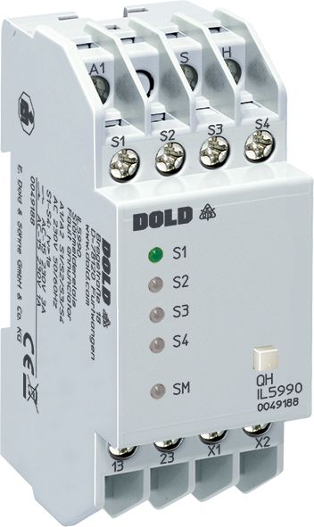
Dold 0058054 IL5990 AC/DC24V 3S surge relay
| Lieske Part No. | 1312718 |
|---|---|
| Mfg Part No | 0058054 |
| EAN-Code | 4030641580544 |
| Manufacturer | Dold |
| Here only | 195,90 EUR
233,12 EUR incl. VAT
|
Further information for Dold 0058054 IL5990 AC/DC24V 3S surge relay
| Technical data | |
| Alarm inputs | 4 |
| Alarm inputs extendable up to | 160 |
| Enclosure design | Distribution board |
| Operating principle | De-energized on trip, Energized on trip |
| Optical signal | LED |
| Width | 35 mm |
| Type | IL 5990 |
| Optional buzzer | |
| Variant | |
| Contact equipping | 2 x 1 NO contact |
| Nominal voltage | AC/DC 24 V |
| Operate delay | 3 s |
Applications
This device is intended for monitoring technical systems in industrial and building automation systems. It is suitable for detecting faults in pumps, motors, heating systems, ventilation systems, or other monitored components. The application is in environments where continuous operational monitoring is required, for example in production plants, energy supply systems, or building technology. The operating temperature ranges from -20 °C to +60 °C, allowing use in indoor and protected outdoor areas.
Functions and Equipment in Detail
The IL5990 features 4 fault alarm inputs, each equipped with an LED for optical indication. The inputs can be switched between operating current principle (output relay is activated in case of fault) and standby current principle (output relay is not activated in case of fault) via bridges X1-X2. The response delay is 3 seconds, suppressing short-term disturbances. The alarm is indicated via two normally open contacts (2 x 1 NO), with one relay designated for collective alarm and another for horn output. A front-mounted reset button QH allows manual acknowledgment of the alarm, thereby deactivating the external alarm device (optional).
Technology Explained Simply
The function is based on detecting signals at fault alarm inputs S1 to S4. When a fault signal is detected, the corresponding LED is activated, and depending on the setting (operating or standby current principle), the output relay is actuated. The 3-second response delay prevents false alarms caused by short-term voltage fluctuations. The output relays are rated for a load of 1 A at AC 230 V and can be operated in an AC 15 switching capacity. The electrical life expectancy is at least 150,000 switching operations, and the mechanical life expectancy is at least 30 million switching operations. The operating voltage range is 0.8 to 1.1 times the nominal voltage, providing high tolerance to voltage fluctuations.
Compatibility and Accessories
The device is expandable and can be extended from 4 to up to 160 fault alarm inputs, with expansion achieved via additional modules such as the IL5991. The bus lines H and S carry low voltage and must not be subjected to external voltages. The optional alarm device IK/SK 8832 is mentioned as accessory. Connections A1, S1–S4, and QH must be connected to the same phase, as well as the normally open contacts 13–14 and 23–24. In cases of inductive or capacitive interference from high-current lines, the use of shielded cables is recommended, with the shield connected to PE.
Mounting and Installation
Mounting is done via a DIN rail (DIN 43880), with the I form factor featuring a depth of 61 mm and bottom-mounted terminal blocks designed for installation distributors. The terminals are rated for conductor cross-sections of 2 x 2.5 mm² (solid) or 2 x 1.5 mm² (stranded wire with sleeve DIN 46228). The tightening torque is 0.8 Nm. The enclosure design is intended for installation distributors, with protection rating IP 40 for the enclosure and IP 20 for the terminals. The operating altitude is limited to below 2000 m.
Advantages in Operation
The device provides clear, structured fault indication with optical signaling via LEDs and enables centralized monitoring of multiple system points. The expandability up to 160 inputs makes it flexible for different system sizes. The adjustable response delay and response principle (operating or standby current) allow application-specific configuration. The robust construction with high mechanical and electrical life expectancy, along with compliance with DIN 19235, ensures reliable operation in industrial environments. Integration into existing monitoring systems is simple thanks to standard connections and DIN rail mounting.

This is an offer of:
79279 Vörstetten
https://industry-electronics.com
Tel. 07666/88499-0
Fax. 07666/88499-111
Diesen Artikel finden Sie unter:
industry-electronics.com/artikel/1312718

Lieske Elektronik e.K.
Reutener Str. 1079279 Vörstetten
https://industry-electronics.com
Tel. 07666/88499-0
Fax. 07666/88499-111
Diesen Artikel finden Sie unter:
industry-electronics.com/artikel/1312718