
Dold 0057515 under-voltage relay 3AC400V
Industrial Material > Industrial relays and contactors > Switching units / measuring, control relay
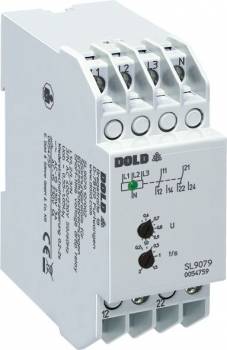
Dold 0057515 under-voltage relay 3AC400V
| Lieske Part No. | 137434 |
|---|---|
| Mfg Part No | 0057515 |
| EAN-Code | 4030641575151 |
| Manufacturer | Dold |
| Here only | 279,94 EUR
333,13 EUR incl. VAT
|
Further information for Dold 0057515 under-voltage relay 3AC400V
| Technical data | |
| 1- / 3-phase | 1, 3 |
| Auxiliary voltage | Without |
| Enclosure design | Switch cabinet |
| Nominal voltage max. | 3 AC 500 V |
| Output contacts | 2 C/O contacts |
| Width | 35 mm |
| Type | SL 9079 |
| Operate delay | |
| Variant | |
| Contact equipping | 2 changeover contacts |
| Nominal voltage | 3AC 400 V |
| Response value | 0,55 - 1,05 Un |
| Time delay | 0,2 - 2 s |
| Variant | For 3p3w systems. Adjustable response value |
Applications
This relay is designed for use in industrial and industrial enclosures where reliable network monitoring is required. It is particularly suitable for systems where uncontrolled restarts after short-term voltage interruptions could cause damage or hazards. Applications include machine controls, drive technology, pump and fan systems, as well as other electrical systems dependent on stable supply voltage. The device can be operated in both three-phase and single-phase networks; in single-phase operation, terminals L1, L2, and L3 must be bridged.
Functions and Features in Detail
The SL9079.12/003 features an adjustable dropout value ranging from 0.55 to 1.05 times nominal voltage (Un), allowing flexible adaptation to different network conditions. The re-energizing delay is adjustable between 0.2 and 2 seconds and serves to generate a defined reset pulse. If a voltage interruption lasting longer than 20 ms is detected at a dropout value of 0.8 Un, the output relay drops out. The green LED, which indicates normal operation, turns off at this point. The relay only re-energizes when all three phase voltages are above the pickup threshold and the set delay time has elapsed. The hysteresis is 4 %, ensuring stable switching behavior without oscillations. The device operates on the standby current principle, where the output relay is not activated in the event of a fault, enhancing safety.
Technology Explained Simply
The relay monitors the voltage of the three phases (L1, L2, L3) individually against the neutral conductor (N). For devices without a neutral conductor connection, phases L1 and L2 are measured against L3. Voltage interruptions are detected starting at a duration of 20 ms when the dropout value is set to 0.8 Un. The response time for a phase failure is approximately 40 ms at a dropout value of 0.8 Un. The nominal voltage is 3 AC 400 V, with the device also capable of handling up to 3 AC 500 V. The nominal frequency is 50/60 Hz, and the nominal power consumption is approximately 8 VA. Input resistances are approximately 150 kΩ. The housing design is intended for enclosures, with a mounting width of 35 mm and a mounting depth of 98 mm. The connection terminals are located at the top, facilitating installation in enclosures with mounting plates and cable ducts.
Compatibility and Accessories
The device is designed for networks without a neutral conductor and can also be operated in single-phase installations. It is compliant with IEC/EN 60255-1 and suitable for use in industrial environments. The contact configuration includes 2 changeover contacts, which can be used for controlling auxiliary circuits or signals. The green LED serves as a visual indicator for normal operation (contact closed). The device can also be configured for fault memory (re-energizing lockout), preventing automatic restarts. Installation is in enclosures, with terminal designations L1, L2, L3, N and output contacts 11-14 and 21-24 clearly defined.
Mounting and Installation
Mounting is performed in enclosures with mounting plates and cable ducts. The mounting width is 35 mm, and the mounting depth is 98 mm. The connection terminals are arranged at the top, enabling easy wiring. In single-phase operation, terminals L1, L2, and L3 must be bridged. The devices are suitable for mounting according to DIN 43880. Installation requires no additional auxiliary voltage, as the device connects directly to the network.
Operational Advantages
The adjustable re-energizing delay ensures that all control components return synchronously to the initial state after a network disturbance, avoiding uncontrolled operating conditions and enhancing operational safety. The rapid detection of voltage interruptions (starting at 20 ms) enables precise response to brief disturbances. The green LED indicator provides visual confirmation of normal operation. The standby current principle ensures that the output relay is not inadvertently activated in the event of a fault. Compliance with IEC/EN 60255-1 guarantees high reliability and safety in industrial applications. The devices are designed for continuous operation at 1.1 times nominal voltage, offering high robustness. The adjustable parameters (dropout value, delay time) allow individual adaptation to specific system requirements.

This is an offer of:
79279 Vörstetten
https://industry-electronics.com
Tel. 07666/88499-0
Fax. 07666/88499-111
Diesen Artikel finden Sie unter:
industry-electronics.com/artikel/137434

Lieske Elektronik e.K.
Reutener Str. 1079279 Vörstetten
https://industry-electronics.com
Tel. 07666/88499-0
Fax. 07666/88499-111
Diesen Artikel finden Sie unter:
industry-electronics.com/artikel/137434