
Dold 0057488 GB9034 40A AC50/60Hz 230V motor brake unit
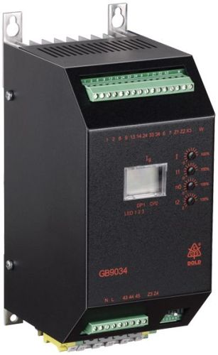
Dold 0057488 GB9034 40A AC50/60Hz 230V motor brake unit
| Lieske Part No. | 100187 |
|---|---|
| Mfg Part No | 0057488 |
| EAN-Code | 4030641574888 |
| Manufacturer | Dold |
| Here only | 1.176,80 EUR
1.400,39 EUR incl. VAT
|
Further information for Dold 0057488 GB9034 40A AC50/60Hz 230V motor brake unit
| Technical data | |
| Braking current adjustable up to max. | 600 A |
| Braking time adjustable up to max. | 320 s |
| Width | 110 mm |
| Type | GB 9034 |
| Automatic standstill monitoring | |
| External brake contactor required | |
| Signalling output | |
| Temperature monitoring | |
| Variant | |
| Auxiliary voltage | Without |
| Braking current | 40 A |
| Nominal voltage | AC 230 V |
| Approvals and Markings | UKCA |
Applications
This brake device is universally applicable in industrial plants where short coast-down times and high safety are required. It is particularly suitable for drives that must be quickly stopped after switching off to avoid accidents or production losses. The device is used in electrical control systems, where it can be integrated into existing circuits without requiring extensive modifications.
Functions and equipment in detail
The device features an automatic standstill monitoring function that monitors the motor status and accordingly ends the braking process. The braking current is switched off either after a set braking time (up to a maximum of 320 seconds) or upon detection of standstill. In standstill-dependent braking, a potential-free signalling contact indicates if the motor has not come to a stop within the maximum braking time. This enables safe fault detection during operation. The temperature monitoring protects the device and the motor from overheating.
Technology explained clearly
Braking is achieved by feeding a direct voltage into the stator winding of the motor via terminals U and V. An external brake contactor is required, which is controlled via terminals 1–2. The supply voltage is connected to L1–L2. The safety time between switching off the motor contactor and switching on the brake contactor prevents induced voltages from damaging the power section. The braking current is 40 A and is adjustable up to a maximum of 600 A. The width of the device is 110 mm.
Compatibility and accessories
The device is compliant with IEC/EN 60947-4-2 and designed for use with induction motors. Optional functions such as star-delta starting, thermistor motor protection or a wide voltage range (200–690 V) can be integrated, but are not part of this variant. The auxiliary voltage is not included in this version.
Mounting and installation
Mounting is carried out in standard enclosures. Terminals L1–L2 are used to connect the operating voltage, while terminals U–V supply the braking direct voltage. The interlock contacts (8–9) and the start contact (6–7) are intended for integration into existing control systems. The connection terminals are clearly labelled to ensure error-free installation.
Advantages in operation
Due to wear-free braking, maintenance frequency is reduced. The shorter coast-down time increases safety and the economic efficiency of the plant. The integrated standstill monitoring and signalling output enable reliable monitoring of the braking process. The device is designed for use in industrial environments and meets the UKCA approval.

This is an offer of:
79279 Vörstetten
https://industry-electronics.com
Tel. 07666/88499-0
Fax. 07666/88499-111
Diesen Artikel finden Sie unter:
industry-electronics.com/artikel/100187

Lieske Elektronik e.K.
Reutener Str. 1079279 Vörstetten
https://industry-electronics.com
Tel. 07666/88499-0
Fax. 07666/88499-111
Diesen Artikel finden Sie unter:
industry-electronics.com/artikel/100187