
Dold 0057430 BF9250.93/008 semiconductor contactor 3xAC10A
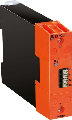
Dold 0057430 BF9250.93/008 semiconductor contactor 3xAC10A
| Lieske Part No. | 1001478 |
|---|---|
| Mfg Part No | 0057430 |
| EAN-Code | 4030641574307 |
| Manufacturer | Dold |
| Here only | 283,48 EUR
337,34 EUR incl. VAT
|
Further information for Dold 0057430 BF9250.93/008 semiconductor contactor 3xAC10A
| Technical data | |
| Approvals | UL |
| Load current up to | 50 A |
| Load voltage up to | AC 480 V |
| Number of poles | 1-pole, 2-pole, 3-pole |
| On/Off Input Control | DC |
| Width | 22,5 mm, 45 mm, 90 mm |
| Type | BF 9250/_ _8 |
| Variant | |
| Auxiliary voltage | DC 9 - 32 V |
| Contact equipping | without signal contact |
| Load current | 3 x AC 10 A |
| Load voltage | AC 24 - 480 V |
| Semiconductor output | 3-pole |
| Approvals and Markings | UL-listed C/US |
| Variant | Switching at zero crossing. |
Applications
This semiconductor contactor is suitable for use in industrial plants where reliable and interference-free switching function is required. Typical applications include switching of heaters, electric motors, valves, and lighting systems. The noiseless switching function makes it particularly suitable for environments where mechanical relays are not acceptable due to switching noise. The switching frequency is high, as it is a semiconductor device without mechanical contacts.
Functions and Equipment in Detail
The device features an integrated protection circuit using varistors, which protects against overvoltages. The turn-on and turn-off delay is each ≤ 1 ms plus 1/2 period, with the 1/2 period being omitted in the instant-switching variant. The connection terminals are clearly labeled: A1/A2 serve as control or operating voltage, L1/L2/L3 as mains connections, and T1/T2/T3 as load outputs. A green LED indicates that voltage is present at terminals A1/A2. The width is 90 mm, making it suitable for mounting on DIN rail.
Technology Explained Simply
The semiconductor contactor operates based on power semiconductors, switching electrical loads without mechanical movement. Switching occurs at the zero crossing of the alternating voltage, which increases component lifespan and reduces electromagnetic interference. Power loss is calculated using the formula P = 1.2 [V] x Ieff. [A] / k [W], where k is the form factor and is 1.11 for sinusoidal current. The maximum peak blocking voltage is ± 1200 Vp, ensuring high insulation strength. The short-circuit current is 400 A at t=10 ms, increasing safety in case of faults.
Compatibility and Accessories
The device complies with IEC/EN 60947-4-2 and IEC/EN 60947-4-3 standards and carries the UL-listed C/US approval. It is designed for continuous operation and can be mounted in horizontal orientation. The ambient temperature is 0 to 40 °C, with current derating required at higher temperatures. The maximum device temperature is 60 °C, with current reduction according to the table. Storage is in the temperature range of -20 to +80 °C.
Mounting and Installation
Mounting is on DIN rail, with the width of 90 mm to be considered. The installation orientation is horizontal, with cooling fins oriented vertically. The connection terminals are clearly labeled, ensuring unambiguous assignment of wires. Control is via a direct voltage in the range of DC 9 to 32 V, with the load voltage being AC 24 to 480 V. Frequency ranges include 50 and 60 Hz.
Operational Advantages
The semiconductor contactor offers a high switching frequency, as it has no mechanical contacts. The noiseless switching reduces operational interference and increases lifespan. The integrated protection circuit using varistors protects against overvoltages. The UL-listed C/US approval enables use in the USA and Canada. Zero-voltage switching minimizes electromagnetic interference and increases system reliability. Mounting on DIN rail facilitates integration into existing enclosures.

This is an offer of:
79279 Vörstetten
https://industry-electronics.com
Tel. 07666/88499-0
Fax. 07666/88499-111
Diesen Artikel finden Sie unter:
industry-electronics.com/artikel/1001478

Lieske Elektronik e.K.
Reutener Str. 1079279 Vörstetten
https://industry-electronics.com
Tel. 07666/88499-0
Fax. 07666/88499-111
Diesen Artikel finden Sie unter:
industry-electronics.com/artikel/1001478