
Dold 0057148 BN9034 25A AC50/60Hz 400V 15S motor brake device
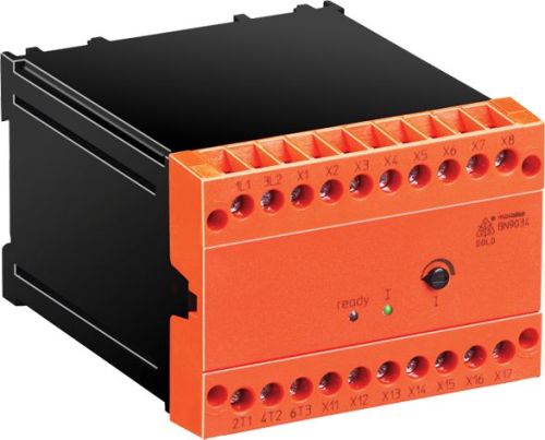
Dold 0057148 BN9034 25A AC50/60Hz 400V 15S motor brake device
| Lieske Part No. | 1001860 |
|---|---|
| Mfg Part No | 0057148 |
| EAN-Code | 4030641571481 |
| Manufacturer | Dold |
| Here only | 510,72 EUR
607,76 EUR incl. VAT
|
Further information for Dold 0057148 BN9034 25A AC50/60Hz 400V 15S motor brake device
| Technical data | |
| Braking current adjustable up to max. | 25 A |
| Braking time adjustable up to max. | 15 s |
| Width | 100 mm |
| Type | BN 9034 |
| Automatic standstill monitoring | |
| Signalling output | |
| Temperature monitoring | |
| Variant | |
| Auxiliary voltage | Without |
| Braking current | 25 A |
| Braking time | 15 s |
| Nominal voltage | AC 400 V |
| Approvals and Markings | UKCA |
Applications
The motor brake device BN 9034 is suitable for industrial drives requiring fast and precise stopping. Typical application fields include sawmills, centrifuges, woodworking machines, textile machines, and conveyor systems. The devices are particularly advantageous in systems where short coast-down times contribute to increased safety and efficiency. The ability to integrate into existing control systems enables flexible installation into existing plants without extensive modifications.
Functions and Equipment in Detail
The device features automatic standstill monitoring, which monitors the motor status and switches off the braking current once standstill is reached. In case of standstill-dependent braking, a potential-free signal contact indicates if the motor has not come to a stop within the maximum braking time. This enables early fault detection and response. Additionally, temperature monitoring is integrated, which can protect the motor from overheating via an optional motor PTC sensor (thermistor). Control is performed via terminals X3 and X4, which are connected to the normally open contact of the motor contactor. The ready" LED indicates that the supply voltage is present, while the "I LED indicates the flow of braking current.
Technology Explained Simply
Braking is achieved by injecting a direct current into the stator winding of the motor, generating a magnetic field that slows down the rotor. The direct voltage is generated from alternating voltage via a single-phase rectifier. The braking time is adjustable and can be set up to 15 seconds, with the braking current adjustable up to 25 A. Braking is activated via the integrated brake contactor, which is switched on after the motor contactor is turned off and after a safety time delay. The devices comply with the standard IEC/EN 60947-4-2, which defines requirements for electronic switching devices for controlling electrical drives. The operating voltage is connected to terminals L1 and L2, while the motor connections are made at T1, T2, and T3.
Compatibility and Accessories
The device is suitable for all asynchronous motors and can be used in combination with optional functions such as star-delta starting or thermistor motor protection. The variant without auxiliary voltage is standard, while the high-voltage version requires an auxiliary voltage (AC 230 V or AC 24 V). The devices are designed for use in industrial high-current installations and meet the requirements for overload category III and pollution degree class 2. The operating temperature range is between 0 °C and +45 °C, and the storage temperature range is between -25 °C and +75 °C. The device is designed for indoor use, as it has protection rating IP 20.
Mounting and Installation
The motor brake device BN 9034 is clipped onto a 35 mm standard rail, enabling easy and quick installation. The connection terminals are designed for a maximum cross-section of 2.5 mm² per terminal, with a maximum torque of 0.8 Nm for the connection. The supply voltage is connected to L1 and L2, while the motor connections are made at T1, T2, and T3. Control is performed via terminals X3 and X4, which are connected to the normally open contact of the motor contactor. The interlock contacts X5 and X6 close when the supply voltage is present. Terminals X14 and X15 are optionally provided for connecting a motor PTC sensor.
Advantages in Operation
Wear-free braking leads to a longer service life of drive components and reduces maintenance costs. The shorter coast-down time increases safety and productivity, especially in systems with high safety requirements. Simple mounting and integration into existing control systems reduce installation time. The integrated standstill monitoring and signal output enable reliable fault detection. The devices are maintenance-free and require no regular maintenance as long as they are operated within the specified operating conditions.

This is an offer of:
79279 Vörstetten
https://industry-electronics.com
Tel. 07666/88499-0
Fax. 07666/88499-111
Diesen Artikel finden Sie unter:
industry-electronics.com/artikel/1001860

Lieske Elektronik e.K.
Reutener Str. 1079279 Vörstetten
https://industry-electronics.com
Tel. 07666/88499-0
Fax. 07666/88499-111
Diesen Artikel finden Sie unter:
industry-electronics.com/artikel/1001860