
Dold 0056881 IL5990AC50/60HZ230V10S surge relay
Industrial Material > Industrial relays and contactors > Switching units / measuring, control relay
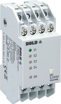
Dold 0056881 IL5990AC50/60HZ230V10S surge relay
| Lieske Part No. | 433678 |
|---|---|
| Mfg Part No | 0056881 |
| EAN-Code | 4030641568818 |
| Manufacturer | Dold |
| Here only | 195,90 EUR
233,12 EUR incl. VAT
|
Further information for Dold 0056881 IL5990AC50/60HZ230V10S surge relay
| Technical data | |
| Alarm inputs | 4 |
| Alarm inputs extendable up to | 160 |
| Enclosure design | Distribution board |
| Operating principle | De-energized on trip, Energized on trip |
| Optical signal | LED |
| Width | 35 mm |
| Type | IL 5990 |
| Optional buzzer | |
| Variant | |
| Contact equipping | 2 x 1 NO contact |
| Nominal voltage | AC 230 V |
| Operate delay | 10 s |
Fault alarm collector
The device functions as a central monitoring element that processes up to 4 fault alarm inputs. These inputs can be set according to either the active current principle (output relay is activated in case of fault) or the idle current principle (output relay remains deactivated in case of fault), with the selection made via bridges X1-X2. The response delay is 10 seconds, enabling filtering of short-term disturbances and reducing false alarms. The inputs are equipped with LED indicators that visually signal the status of each fault.
Functions and equipment in detail
The IL5990 features two normally closed contacts (2 x 1 normally closed contact) as contact configuration, designated for collective alarm and horn output. The rated voltage is AC 230 V at a rated frequency of 50/60 Hz. Inputs S1 to S4 and the supply voltage A1-A2 must be connected to the same phase to ensure correct operation. The reset button QH on the front panel allows manual resetting of alarms and is also intended for external alarm devices.
Technology explained clearly
The technology is based on a relay system that activates the corresponding output relays upon detection of a fault via the inputs. The 10-second response delay ensures that only disturbances lasting long enough (at least 100 ms) are detected. Visual indication is provided by LEDs integrated directly into the device. The outputs are rated for a load of 1 A at AC 230 V (AC 15) and have an electrical life of at least 150,000 switching operations. The mechanical life is at least 30 million switching operations.
Compatibility and accessories
The device is expandable from 4 to up to 160 fault alarm inputs, using expansion devices such as the IL5991. Communication between devices occurs via bus lines H and S, which carry low voltage and must not be subjected to foreign voltages. As an accessory, the alarm device IK/SK 8832 is available, which can be controlled via the reset button QH. The devices are available in two housing forms: I-type with 61 mm depth and bottom-mounted terminals for installation distributors according to DIN 43880, and S-type with 100 mm depth and top-mounted terminals for enclosures with mounting plate.
Mounting and installation
Mounting is done via a DIN rail (DIN standard) in the installation distributor. The terminal connections are designed for conductor cross-sections of 2 x 2.5 mm² (solid) or 2 x 1.5 mm² (stranded wire with sleeve DIN 46228). The tightening torque is 0.8 Nm. The terminals are equipped with self-lifting connection washers, enabling quick and secure connections. The operating temperature ranges from -20 °C to +60 °C, and the storage temperature ranges from -25 °C to +60 °C. The operating altitude is limited to below 2000 m.
Advantages in operation
The device offers high reliability with a mechanical life of over 30 million switching operations and an electrical life of at least 150,000 switching operations. The expandability up to 160 inputs enables flexible scaling for different plant sizes. The integrated LEDs and the front-mounted reset button simplify operation and maintenance. Compliance with DIN 19235 ensures standardized and safe integration into existing monitoring systems. The housing protection rating is IP 40 and the terminals are IP 20, protecting against mechanical impacts and contact, with the housing made of thermoplastic material with V0 behavior according to UL Subject 94.
Housing design and width
The device is designed in I-type for installation distributors, with a width of 35 mm and a depth of 61 mm. The housing design is intended for installation distributors, with terminals located at the bottom. The housing protection rating IP 40 and terminal protection rating IP 20 ensure sufficient protection against dust and contact. The devices are designed for continuous operation and meet requirements for electrical and mechanical life as well as electromagnetic compatibility (e.g. ESD, HF radiation, fast transients, surge voltage). The conductor connection terminals are designed for use with flat terminals with self-lifting connection washers.
Fault alarm inputs and expansion
The four integrated fault alarm inputs are equipped with LEDs and can be switched between active current and idle current principles via bridges X1-X2. Expansion up to 160 inputs is achieved using additional expansion devices such as the IL5991. Bus lines H and S carry low voltage and must not be subjected to foreign voltages. For inductive or capacitive interference from high-current lines, the use of shielded cables is recommended, with the shielding connected to PE.
Approvals and environmental conditions
The device complies with standards IEC/EN 60947-5-1 for switching devices, IEC/EN 60529 for protection ratings, IEC/EN 60664-1 for creepage and clearance distances, and IEC/EN 61000-4-2 to -5 for EMC requirements. Radio frequency interference suppression meets Class B limit values according to EN 55011. Vibration resistance is 0.35 mm amplitude at frequencies from 10 to 55 Hz. Climate resistance is defined according to 20/060/04 per IEC/EN 60068-1. The operating temperature ranges from -20 °C to +60 °C, and the storage temperature ranges from -25 °C to +60 °C. The operating altitude is limited to below 2000 m.
Connection and wiring
Connections A1, S1-S4, and QH must be connected to the same phase. The normally closed contacts 13-14 and 23-24 must also be connected to the same phase. Bus lines H and S carry low voltage and must not be subjected to foreign voltages. The terminals are designed for conductor cross-sections of 2 x 2.5 mm² (solid) or 2 x 1.5 mm² (stranded wire with sleeve DIN 46228). The tightening torque is 0.8 Nm. The terminals are equipped with self-lifting connection washers, enabling quick and secure connections.
Accessories and expansion options
As an accessory, the alarm device IK/SK 8832 is available, which can be controlled via the reset button QH. Expansion up to 160 fault alarm inputs is achieved using additional expansion devices such as the IL5991. Communication between devices occurs via bus lines H and S, which carry low voltage and must not be subjected to foreign voltages. The devices are available in two housing forms: I-type with 61 mm depth and bottom-mounted terminals for installation distributors according to DIN 43880, and S-type with 100 mm depth and top-mounted terminals for enclosures with mounting plate.

This is an offer of:
79279 Vörstetten
https://industry-electronics.com
Tel. 07666/88499-0
Fax. 07666/88499-111
Diesen Artikel finden Sie unter:
industry-electronics.com/artikel/433678

Lieske Elektronik e.K.
Reutener Str. 1079279 Vörstetten
https://industry-electronics.com
Tel. 07666/88499-0
Fax. 07666/88499-111
Diesen Artikel finden Sie unter:
industry-electronics.com/artikel/433678