
Dold 0056451 thermistor motor protection relay 230V
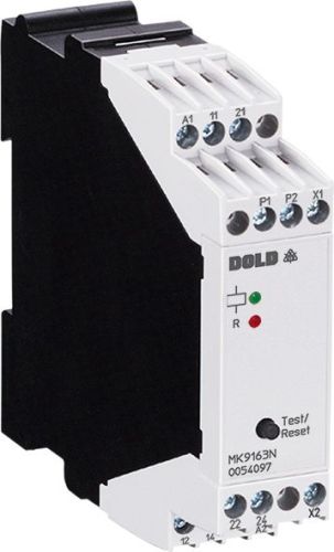
Dold 0056451 thermistor motor protection relay 230V
| Lieske Part No. | 1002258 |
|---|---|
| Mfg Part No | 0056451 |
| EAN-Code | 4030641564513 |
| Manufacturer | Dold |
| Here only | 94,97 EUR
113,01 EUR incl. VAT
|
Further information for Dold 0056451 thermistor motor protection relay 230V
| Technical data | |
| Auxiliary voltage | AC, AC/DC |
| Classification | Thermistor-Motorschutz |
| Enclosure design | Switch cabinet |
| Measuring range max. | > 3.8 kΩ |
| Output contacts | 2 C/O contacts |
| Width | 22,5 mm |
| Type | MK 9163N |
| Variant | |
| Contact equipping | 2 changeover contacts |
| Nominal voltage | AC 230 V |
| Terminal type | fixed terminal blocks with screw terminals |
| Approvals and Markings | UL-rec. C/US, UKCA |
| Variant | With RESET and test function via built in button. At X1/X2 RESET function only |
Applications
This device is designed for use in industrial plants where reliable temperature monitoring of motors and other thermally stressed components is required. It is particularly suitable for applications where rapid fault localization is important, such as in manufacturing, process engineering, or machine building. Monitoring is performed via thermistors integrated into the components to be monitored. When the trigger temperature is reached or if a wire break occurs in the sensor circuit, the device signals a fault.
Functions and equipment in detail
The MK 9163N features two changeover contacts as output contacts, which can be used for controlling auxiliary circuits or signal indication. The contact position and auxiliary voltage are indicated via integrated LED displays. The variant with reset and test function allows manual fault acknowledgment via a pushbutton on the device. Additionally, the fault can be remotely reset by bridging terminals X1/X2, where only the reset function is available. The test function allows testing the system during normal operation by pressing the pushbutton – the device then signals a fault as long as the button is held down.
Technology explained simply
The relay's input circuit detects temperature exceedances in the range of 3.2 to 3.8 kΩ and interruptions in the sensor circuit at resistances above 3.8 kΩ. The reset value lies between 1.5 and 1.8 kΩ. The measurement circuit load is less than 5 mW at a resistance of 1.5 kΩ, and the measurement voltage is limited to a maximum of 2 V. The auxiliary voltage is AC 230 V, although other voltages such as AC 110 V, 400 V, or DC 24 V are also supported. The voltage range is 0.8 to 1.1 times the rated voltage for AC. For DC voltages with 10 % ripple, the range is 0.9 to 1.25 times, and with 48 % ripple, it is 0.8 to 1.1 times. The rated consumption is 1.5 VA for AC and 0.85 W for DC. The switching-on delay is less than 40 ms, and the switching-off delay is less than 100 ms. The maximum bridging time during auxiliary voltage failure is 20 ms.
Compatibility and accessories
The device is specified according to EN 60947-5-1 and EN 60947-8 and carries the approvals UL-rec. C/US and UKCA. The terminal type consists of fixed terminal blocks with screw terminals. Connection options include 2 x 1.5 mm² stranded wire with ferrule and plastic sleeve, and 2 x 2.5 mm² solid wire according to DIN 46 228-1/-2/-3/-4. Optional plug-in terminal blocks are available, enabling quick device replacement. The width is 22.5 mm, allowing installation in standard enclosures. The operating temperature range is -20 °C to +60 °C, and the storage temperature range is also -20 °C to +60 °C. The maximum operating altitude is 2000 m above sea level.
Mounting and installation
The device is mounted in enclosures and requires secure fastening to a vertical mounting surface. Connections are made via the fixed screw terminals. The auxiliary voltage is connected to A1/A2, and the thermistors to P1/P2. The remote reset function is implemented via X1/X2, requiring a potential- and voltage-free normally closed contact. Galvanic isolation between the input and the measurement input P1/P2 is not present.
Advantages in operation
Reliable temperature monitoring and rapid fault localization are key advantages. The integrated LED display enables quick visual inspection of the operating status. The ability to acknowledge faults via pushbutton or remote reset reduces operational downtime. The mechanical life is at least 30 million switching operations, and the electrical life at 4 A, AC 230 V, and cosϕ = 0.6 is 1.5 million switching operations. Short-circuit resistance is specified according to IEC/EN 60947-5-1, with a 6 A gG/gL fuse required for openers and 10 A gG/gL for closers. The device is designed for continuous operation and meets requirements for insulation class and pollution degree 4.

This is an offer of:
79279 Vörstetten
https://industry-electronics.com
Tel. 07666/88499-0
Fax. 07666/88499-111
Diesen Artikel finden Sie unter:
industry-electronics.com/artikel/1002258

Lieske Elektronik e.K.
Reutener Str. 1079279 Vörstetten
https://industry-electronics.com
Tel. 07666/88499-0
Fax. 07666/88499-111
Diesen Artikel finden Sie unter:
industry-electronics.com/artikel/1002258