
Dold 0056266 SL9087.12 3AC50/60Hz 400/230V phase monitor
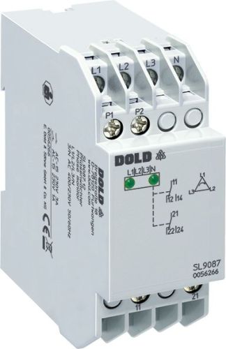
Dold 0056266 SL9087.12 3AC50/60Hz 400/230V phase monitor
| Lieske Part No. | 1002077 |
|---|---|
| Mfg Part No | 0056266 |
| EAN-Code | 4030641562663 |
| Manufacturer | Dold |
| Here only | 176,03 EUR
209,48 EUR incl. VAT
|
Further information for Dold 0056266 SL9087.12 3AC50/60Hz 400/230V phase monitor
| Technical data | |
| 1- / 3-phase | 3 |
| Auxiliary voltage | Without |
| Enclosure design | Switch cabinet |
| Measuring range max. | 400 V |
| Output contacts | 1 C/O contact, 2 C/O contacts |
| Standard measuring range | 3/N AC 400/230 V |
| Width | 35 mm |
| Type | SL 9087 |
| Variant | |
| Contact equipping | 2 changeover contacts |
| Nominal voltage | 3AC 400/230 V 50/60 Hz |
Applications
The phase monitor SL9087.12 is suitable for installations with motor-driven loads such as pumps, fans, conveyor belts, or elevator systems, where stable and symmetrical network voltage is required for safe operation. It is used in industrial and commercial installations, where early detection of network faults helps prevent machine damage and production downtime.
Functions and Equipment in Detail
The device detects undervoltage at approximately 70 % of nominal voltage (0.7 ± 0.15 x U_N) and responds to a phase sequence that deviates from the preset order. An asymmetry of approximately 20° angular asymmetry is also detected. In the event of a network fault, the output contact (11-14) opens, triggering a shutdown or alarm. The output contacts are configured as 2 changeover contacts, enabling two independent switching functions. The contacts are made of AgNi 0.15 + 0.3 μm AU, ensuring high switching life and low contact resistance. The electrical life is at least 600,000 switching cycles at 1 A and AC 230 V, while the mechanical life is specified as ≥ 10^8 switching cycles.
Technology Explained Simply
The phase monitor operates on the principle of residual current, where the output relay is not activated in the event of a fault, but is energized during normal operation. This means the contacts are closed during normal operation and open during a fault. The current consumption is approximately 7 mA per phase L1 and L2, while L3 consumes about 1.5 mA. The nominal power consumption is approximately 3.5 VA. The response delay is 100 to 300 ms, and the switching-on delay is 15 to 30 ms. The hysteresis is defined as ≤ 6 % of nominal voltage to ensure stable switching behavior during voltage fluctuations.
Compatibility and Accessories
The device is designed for 3-phase networks with neutral conductor and can also be operated without a neutral conductor, leaving the N terminal open. It is designed for operating voltages of 3/N AC 400/230 V at frequencies of 50/60 Hz, with a frequency range of 45 to 65 Hz supported. The operating temperature ranges from -20 °C to +60 °C, and the storage temperature ranges from -40 °C to +70 °C. The operating altitude is limited to ≤ 2000 m. Compliance with the standard IEC/EN 60255-1 is ensured, allowing use in industrial installations.
Mounting and Installation
Mounting is performed in enclosures with mounting plate and cable duct. The top-mounted connection terminals allow for easy wiring. The width of 35 mm corresponds to the standard module grid, enabling seamless integration into common switchboards. The connection terminals are designed for connection with wires, with a maximum thermal current load per contact of 4 A. The switching capacity according to AC 15 is 3 A/AC 230 V for closing contacts and 1 A/AC 230 V for opening contacts.
Advantages in Operation
Early detection of network faults enables preventive maintenance and prevents costly damage to connected devices. The LED indicators signal the operating status: the left LED lights up for correct operating voltage, and the right LED for correct measurement voltage. In the event of a fault, neither LED lights up, and the contact opens. Simple installation without auxiliary voltage reduces wiring complexity. High operational safety and system availability are ensured through continuous monitoring.

This is an offer of:
79279 Vörstetten
https://industry-electronics.com
Tel. 07666/88499-0
Fax. 07666/88499-111
Diesen Artikel finden Sie unter:
industry-electronics.com/artikel/1002077

Lieske Elektronik e.K.
Reutener Str. 1079279 Vörstetten
https://industry-electronics.com
Tel. 07666/88499-0
Fax. 07666/88499-111
Diesen Artikel finden Sie unter:
industry-electronics.com/artikel/1002077