
Dold 0055930 MK3096N.48 DC24V coupling module
Industrial Material > Industrial relays and contactors > Electronic modules
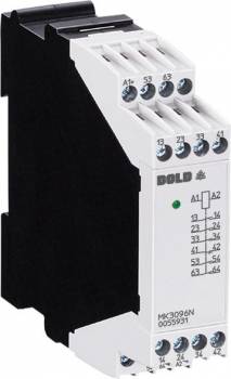
Dold 0055930 MK3096N.48 DC24V coupling module
| Lieske Part No. | 926925 |
|---|---|
| Mfg Part No | 0055930 |
| EAN-Code | 4030641559304 |
| Manufacturer | Dold |
| Here only | 115,19 EUR
137,08 EUR incl. VAT
|
Further information for Dold 0055930 MK3096N.48 DC24V coupling module
| Technical data | |
| Connection | Pluggable cage clamp terminals, Pluggable screw terminals, Screw terminals |
| Enclosure design | Switch cabinet |
| Output contacts max. | 1 NC contact, 5 NO contacts |
| Thermal current Ith max. | 5 A |
| Width | 22,5 mm |
| Type | MK 3096N |
| Variant | |
| Contact equipping | 3 NO contacts, 1 NC contact |
| Nominal voltage | DC 24 V |
| Terminal type | screw terminal fixed |
| Approvals and Markings | CCC |
Applications
This module is used in industrial automation, particularly in systems requiring secure signal transmission and state monitoring. It is suitable for connecting safety switching devices with control systems, for example in machine controls, drive technology, or packaging industry. The forced-guided contacts ensure that the switching state is correctly detected even in the event of mechanical disturbances or contact wear, which is crucial for safety functions.
Functions and Equipment in Detail
The coupling module features a contact configuration of 3 normally closed contacts and 1 normally open contact, with all contacts being forced-guided. This means that the normally open contact is mechanically linked to the normally closed contacts, allowing its state to be monitored. The maximum number of output contacts is 6, with the normally closed contacts used for main functions and the normally open contact for state monitoring. The contacts are designed for continuous operation, with a mechanical life of at least 20 million switching cycles.
Technology Explained Simply
The forced-guided contacts are a central feature of the module. They ensure that the normally open contact assumes the same mechanical state as the normally closed contacts — i.e., open when the normally closed contacts are closed, and vice versa. This enables secure monitoring, for example in safety circuits, where a defective contact must be detected. The switching function operates on a DC voltage of 24 V, with a rated power consumption of 0.6 W. The switching capacity is up to 1250 VA (AC) or 200 W (DC), with switching voltages ranging from 10 V to 250 V (DC) or 400 V (AC). The switching frequency is limited to a maximum of 10 switching cycles per second.
Compatibility and Accessories
The module is equipped with fixed screw terminals suitable for conductor cross-sections up to 2.5 mm² solid (DIN 46228-1/-2/-3/-4) or 1.5 mm² stranded wire with ferrule and plastic collar. Alternatively, removable spring terminals and removable screw terminals are available, offering flexible integration into existing control systems. The optional use of plug-in connection blocks enables quick replacement of the device. The terminals are designed for secure and durable connections.
Mounting and Installation
The coupling module is mounted in enclosures and is designed for installation on 35 mm standard rails (DIN rail). The module width of 22.5 mm allows for compact placement in tight control systems. The terminals are designed for connection with solid conductors, with maximum cross-sections and standards (DIN 46228) to be observed. Mounting is done by screwing the terminals to the conductors, with designated connection points clearly marked (A1/A2 for operating voltage, 13/14, 23/24, 33/34, 43/44, 53/54, 63/64 for normally closed contacts, 21/22, 41/42, 61/62 for normally open contacts).
Operational Advantages
The use of forced-guided contacts increases safety and reliability in critical applications. Contact multiplication allows multiple switching circuits to be powered from a single signal, reducing the number of required relays. The compact design and standard width of 22.5 mm facilitate integration into existing control systems. The maximum thermal load capacity of 5 A per contact and the high mechanical life of over 20 million switching cycles ensure long-term operation under industrial conditions. The CCC (China Compulsory Certification) approval ensures compliance with applicable safety standards in China.
Operating Conditions
The device is designed for operation in a temperature range of -20 °C to +60 °C, with storage possible up to -40 °C and +60 °C. The operating altitude is limited to a maximum of 2000 m above sea level. The creepage and clearance distances correspond to pollution degree 2 with a rated impulse withstand voltage of 4 kV, ensuring electrical safety. EMC requirements are met in accordance with IEC/EN 61000-4-2 to -4-5, including immunity to electrostatic discharge (8 kV), high-frequency radiation (10 V/m), and fast transients (4 kV). Radiated emissions comply with Class B limits according to EN 55011.
Approvals and Markings
The module carries the CCC approval, required for use in China. Compliance with standards IEC/EN 60947-5-1 (switching devices for control gear) and IEC 61810-3 (forced-guided contacts) is guaranteed. EMC requirements are fulfilled in accordance with the specified IEC/EN standards, ensuring reliability in electromagnetically noisy environments.
Switching Capacity and Lifespan
The switching capacity according to AC 15 is 3 A at AC 230 V for normally closed contacts and 2 A at AC 230 V for normally open contacts. For DC 13, the switching capacity is 1 A at DC 24 V for both contact types. The electrical life is 1.5 x 10⁵ switching cycles for normally closed contacts at 3 A/AC 230 V and 3 x 10⁵ switching cycles at 2 A/AC 230 V. The mechanical life is at least 20 x 10⁶ switching cycles. The maximum short-circuit withstand requires a fuse of 10 A gL according to IEC/EN 60947-5-1.
Connection and Wiring
The connection terminals are clearly marked: A1/A2 for operating voltage, normally closed contacts (13/14, 23/24, 33/34, 43/44, 53/54, 63/64), and normally open contacts (21/22, 41/42, 61/62). Wiring is done via screw terminals, with maximum conductor cross-sections (2.5 mm² solid, 1.5 mm² stranded) and standards (DIN 46228) to be observed. The terminals are designed for secure and durable connections, with mounting done using fixed screw terminals.
Approvals and Markings
- CCC
- IEC/EN 60947-5-1
- IEC 61810-3
- EN 55011
- IEC/EN 61000-4-2 to -4-5

This is an offer of:
79279 Vörstetten
https://industry-electronics.com
Tel. 07666/88499-0
Fax. 07666/88499-111
Diesen Artikel finden Sie unter:
industry-electronics.com/artikel/926925

Lieske Elektronik e.K.
Reutener Str. 1079279 Vörstetten
https://industry-electronics.com
Tel. 07666/88499-0
Fax. 07666/88499-111
Diesen Artikel finden Sie unter:
industry-electronics.com/artikel/926925