
Dold 0055727 motor protection switch MK9003.12/11120 ATEX AC230V
Industrial Material > Control devices / Pilot devices > Motor protection switch
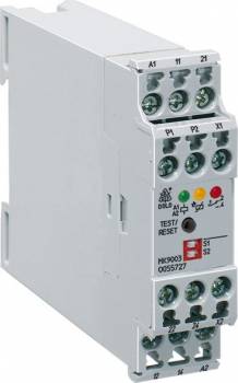
Dold 0055727 motor protection switch MK9003.12/11120 ATEX AC230V
| Lieske Part No. | 1966468 |
|---|---|
| Mfg Part No | 0055727 |
| EAN-Code | 4030641557270 |
| Manufacturer | Dold |
| Here only | 303,49 EUR
361,15 EUR incl. VAT
|
Further information for Dold 0055727 motor protection switch MK9003.12/11120 ATEX AC230V
| Technical data | |
| Classification | Thermistor-Motorschutz |
| Enclosure design | Switch cabinet |
| Measuring range max. | > 3.1 kΩ |
| Output contacts | 2 C/O contacts |
| Width | 22,5 mm |
| Type | MK 9003 ATEX |
| Variant | |
| Auxiliary voltage | AC 230 V |
| Contact equipping | 2 changeover contacts |
| Approvals and Markings | ATEX |
| Variant | Function programmable on S1 and S2. With short circuit detection. With safe separation |
Applications
This device is intended for temperature monitoring of standard and explosion-protected motors in hazardous areas. It is used in installations where flammable gases or dusts are present and meets the requirements of EN 60079-14 and EN 60079-0. The ATEX certification ensures its use in explosive environments according to European explosion protection directives. Applications include industrial plants such as those in the chemical industry, process engineering, or material handling, where reliable motor monitoring is required.
Functions and Equipment in Detail
The relay features two changeover contacts as output contacts, which can be used to control auxiliary devices or alarms. The functions are programmable via DIP switches S1 and S2, allowing selection of various operating modes: without RESET function (without memory behavior), with RESET function (with memory behavior), activation upon power-up (power-on acknowledgment), or with RESET function even after power-up. The voltage-free memory ensures that the fault condition is retained even during brief power interruptions. A push-button enables manual reset, and remote reset is also possible via terminals X1/X2 (normally closed contact).
Technology Explained Simply
The device operates on the principle of rest current, where the output relay is not activated in the absence of a fault, but generates a signal in the output contacts only upon detection of a fault (e.g., overtemperature, wire break, short circuit). LED indicators display the operating status: auxiliary voltage, contact position, and overtemperature, wire break, or short circuit in the sensor circuit. Measurement is performed via an input that can control up to three or six thermistors. The maximum measurement range is over 3.1 kΩ. The auxiliary voltage is AC 230 V, enabling standard power supply in industrial installations.
Compatibility and Accessories
The device is designed for use with thermistors integrated into the motor. Connection examples in the datasheet show wiring for safe separation in accordance with EN 61140, EN 60947-1, with an insulation strength of 6 kV/2 between auxiliary voltage and measurement circuit, auxiliary voltage and contacts, measurement circuit and contacts, and between the two contacts (with 2 changeover contacts). The width is 22.5 mm, allowing installation in standard enclosures.
Mounting and Installation
Mounting is carried out in enclosures, with the width of 22.5 mm determining the mounting height. The terminal connections are intended for connecting the thermistors, auxiliary voltage, and output contacts. Safe separation between electrical circuits must be considered during installation to ensure the required insulation. The connection examples in the datasheet serve as a guide for correct wiring.
Advantages in Operation
The programmable functions allow flexible adaptation to different applications. The LED indicators enable quick fault localization, reducing maintenance time. The safe separation and voltage-free memory increase system reliability. Compliance with ATEX certification ensures safe operation in explosive environments. The device is designed for industrial use and meets the requirements of standards EN 60947-5-1, EN 60947-8, EN 60079-14, EN 61508, EN 50495, and EN 13849.

This is an offer of:
79279 Vörstetten
https://industry-electronics.com
Tel. 07666/88499-0
Fax. 07666/88499-111
Diesen Artikel finden Sie unter:
industry-electronics.com/artikel/1966468

Lieske Elektronik e.K.
Reutener Str. 1079279 Vörstetten
https://industry-electronics.com
Tel. 07666/88499-0
Fax. 07666/88499-111
Diesen Artikel finden Sie unter:
industry-electronics.com/artikel/1966468