
Dold 0055102 SL5881.12 DC12-280V UH DC24V insulation monitor 5-200 kΩ
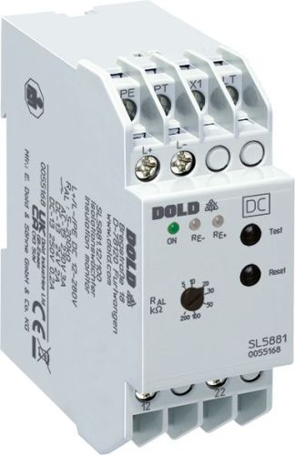
Dold 0055102 SL5881.12 DC12-280V UH DC24V insulation monitor 5-200 kΩ
| Lieske Part No. | 1001720 |
|---|---|
| Mfg Part No | 0055102 |
| EAN-Code | 4030641551025 |
| Manufacturer | Dold |
| Here only | 255,83 EUR
304,44 EUR incl. VAT
|
Further information for Dold 0055102 SL5881.12 DC12-280V UH DC24V insulation monitor 5-200 kΩ
| Technical data | |
| Enclosure design | Switch cabinet |
| IMD type | DC |
| Nominal voltage IT system | DC 12 - 280 V, DC 24 - 500 V |
| Response value | 5 - 500 kΩ |
| Response value type | Adjustable |
| Width | 35 mm |
| Type | SL 5881 |
| Earth fault indicator | |
| Variant | |
| Alarm value | 5 - 200 kOhm |
| Auxiliary voltage | DC 24 V |
| Contact equipping | 2 changeover contacts |
| Nominal voltage | DC 12 - 280 V |
| Time delay | without |
| Approvals and Markings | UKCA |
| Variant | With auxiliary supply |
Applications
The insulation monitor is specifically designed for pure DC systems operating in the voltage range of DC 12 to 280 V. It is suitable for installations requiring continuous monitoring of the insulation condition to warn of faults before they occur. The selective earth fault detection for L+ and L- enables quick fault localization, reducing maintenance and repair times. Applications include industrial environments and rail vehicle technology, where the reliability of electrical systems is critical.
Functions and Equipment in Detail
The device features two changeover contacts as contact configuration, which drop out in the event of a fault (rest current principle). The trip threshold for earth fault is adjustable via a potentiometer on the front of the device and ranges from 5 to 200 kOhm. Indication is provided via LEDs: a green LED indicates operational readiness, while red LEDs indicate earth fault on L+ (RE+) or L- (RE-). The display allows direct visual control of the operating status. Additionally, an internal reset button and a test button are provided, with external buttons being connectable.
Technology Explained Simply
The insulation monitor monitors the unsymmetrical insulation resistance between the conductors L+ and L- relative to ground. When the resistance falls below the set alarm threshold, the fault is indicated by the corresponding red LED and the output relay switches off. Programming is done via a bridge between terminals LT and X1: if the bridge is present, hysteresis behavior is activated, allowing the device to automatically return to the good state when the insulation condition improves. Without the bridge, the fault condition remains stored until reset via the reset button or by switching off the auxiliary voltage.
Compatibility and Accessories
The device is designed in accordance with standard IEC/EN 61557-8. It is intended for use in IT systems with DC 12 to 280 V, and on request, variants with a voltage range up to DC 500 V and a measurement range of 20 to 500 kOhm are available. Mounting is either on a DIN rail or by screw mounting. Terminal designations include connections for the monitored IT system (A1, A2), the protective conductor (PE), and connections for external test (PT, X1) and reset buttons (LT, X1).
Mounting and Installation
Mounting is in enclosures with a depth of 98 mm. The connection terminals are arranged at the top, facilitating integration into enclosures with mounting plate and cable duct. DIN rail or screw mounting allows flexible installation. The terminals are clearly labeled to ensure unambiguous assignment of conductors.
Advantages in Operation
The insulation monitor provides preventive protection against fires and equipment damage through early detection of earth faults. The simple adjustment of the trip threshold via a potentiometer allows application-specific adaptation. The selective indication of earth fault on L+ or L- accelerates fault localization. The integrated test and reset functions support maintenance and functional testing of the device. Operational readiness is indicated by the green LED, making the device status always visible.

This is an offer of:
79279 Vörstetten
https://industry-electronics.com
Tel. 07666/88499-0
Fax. 07666/88499-111
Diesen Artikel finden Sie unter:
industry-electronics.com/artikel/1001720

Lieske Elektronik e.K.
Reutener Str. 1079279 Vörstetten
https://industry-electronics.com
Tel. 07666/88499-0
Fax. 07666/88499-111
Diesen Artikel finden Sie unter:
industry-electronics.com/artikel/1001720