
Dold 0054172 voltage relay 0.2-2 s
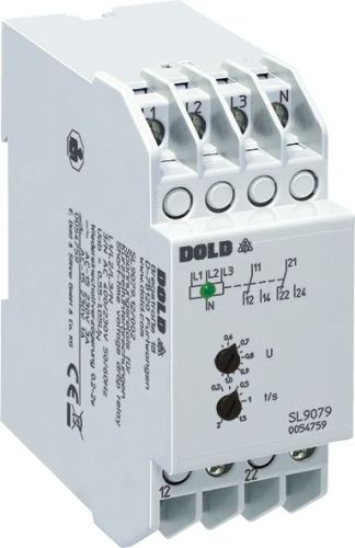
Dold 0054172 voltage relay 0.2-2 s
| Lieske Part No. | 1152419 |
|---|---|
| Mfg Part No | 0054172 |
| EAN-Code | 4030641541729 |
| Manufacturer | Dold |
| Here only | 289,40 EUR
344,39 EUR incl. VAT
|
Further information for Dold 0054172 voltage relay 0.2-2 s
| Technical data | |
| 1- / 3-phase | 1, 3 |
| Auxiliary voltage | Without |
| Enclosure design | Switch cabinet |
| Nominal voltage max. | 3 AC 500 V |
| Output contacts | 2 C/O contacts |
| Width | 35 mm |
| Type | SL 9079 |
| Operate delay | |
| Variant | |
| Contact equipping | 2 changeover contacts |
| Nominal voltage | 3AC 400 V |
| Response value | 0,8 - 1,05 Un |
| Time delay | 0,2 - 2 s |
| Variant | For 3p3w systems. Adjustable response value. With transformator for mains with harmonic content |
Applications
This relay is used in control systems, particularly in contactor and PLC systems, to prevent uncontrolled states after short network interruptions. Such interruptions can be caused by lightning strikes or switching operations in the network. In such cases, individual contactors may drop out while others remain activated, leading to undefined operating conditions. The SL9079.12/103 detects such short-term interruptions from a duration of 20 ms and responds to return control systems to a defined initial state.
Functions and equipment in detail
The device features two changeover contacts as output contacts, which can be used to control external loads. The pickup values are adjustable in the range of 0.8 to 1.05 times nominal voltage, with the drop-out value also adjustable within the range of 0.8 to 1.05 UN. The re-energizing delay is adjustable between 0.2 and 2 seconds to generate an extended reset pulse. This enables control systems to be safely and controlled restarted after a network interruption. The green LED indicator signals the good condition, meaning the output relay is activated and the voltage is within the specified range.
Technology explained simply
The relay measures the voltage of each phase against the neutral conductor (for devices without an N connection, L1 and L2 are measured against L3). If at least one phase falls below the set drop-out value, the LED turns off and the output relay drops out. Only when all three phases are again above the pickup value does the relay re-engage after the adjustable delay time. The response time for a phase failure is approximately 40 ms at a pickup value of 0.8 UN. The hysteresis is 4 %, ensuring stable switching behavior. The device is designed for a nominal frequency of 50/60 Hz and consumes approximately 8 VA. The input resistances are approximately 150 kΩ.
Compatibility and accessories
The SL9079.12/103 is suitable for single-phase and three-phase connections. For single-phase use, terminals L1, L2, and L3 must be bridged. Phase sequence is arbitrary, simplifying installation. The device is compliant with IEC/EN 60255-1 and can also be configured for fault memory (re-energizing lockout). It is optionally available without a neutral conductor connection. The SL 9079 housing type is designed for enclosures with mounting plate and cable duct, with a depth of 98 mm.
Mounting and installation
The device is mounted in enclosures and is designed for installation on a DIN rail. The connection terminals are located at the top, facilitating wiring in the enclosure. The maximum nominal voltage is 3 AC 500 V, and the device is designed for continuous overload capacity of 1.1 times nominal voltage. The contact materials consist of AgNi, ensuring high switching capacity and long service life.
Advantages in operation
Thanks to the adjustable re-energizing delay, the device can ensure that all control components are synchronized after a network interruption. This prevents unwanted restarts and protects the system from damage. The green LED indicator allows for quick visual inspection of the operating status. Configuring the device for fault memory (re-energizing lockout) provides additional safety by preventing automatic restarts until a manual reset is performed. Compatibility with single-phase connections and independence from phase sequence increase installation flexibility.

This is an offer of:
79279 Vörstetten
https://industry-electronics.com
Tel. 07666/88499-0
Fax. 07666/88499-111
Diesen Artikel finden Sie unter:
industry-electronics.com/artikel/1152419

Lieske Elektronik e.K.
Reutener Str. 1079279 Vörstetten
https://industry-electronics.com
Tel. 07666/88499-0
Fax. 07666/88499-111
Diesen Artikel finden Sie unter:
industry-electronics.com/artikel/1152419